Additional Installation Tip s
7 AdditionalInstallationTips
When experiencing communication problems in noisy environments or when
operating close to temperature limits, the following recommendations are t o be
noticed.
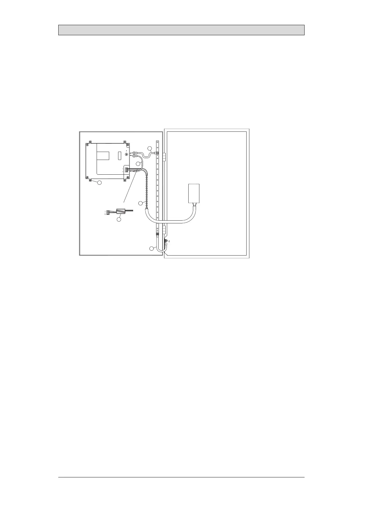
7.1 Groundingtheoperatorpanel
1
2
3
4
5
6
5350
Door
Operator panel
Ferrite core
Mounting plate in the cabinet
Power supply
24 V DC
The mounting clamps of the operator panel do not provide a secure grounding
connection between the panel and the device cabinet, see 1 in drawing above.
1.
Connect a wire, that is sized correctly according to local electrical codes,
between the quick-connect terminal connector on the operator panel and the
chassis of the panel, see 2 in drawing above.
2.
Connect a wire or grounding braid, that is sized correctly according to local
electrical codes, between the chassis of the operator panel and the closest
grounding point on the door, see 3 in drawing above.
3.
Connect a strong but short grounding braid between the door and the device
cabinet,see 4 in drawing above.
4.
Twist the cables onto the 24
V DC feed, see 5 in drawing above.
2 turns around the ferrite core provide 4 times the suppression of 1 turn.
3 turns around the ferrite
core provide 9 times the suppression of 1 turn.
Connect a wire or grounding braid, that is sized correctly according to local
electrical codes, between the chassis of the operator panel and the c losest
grounding point.
BeijerElectronics, MAEN330
20