Installation
6.
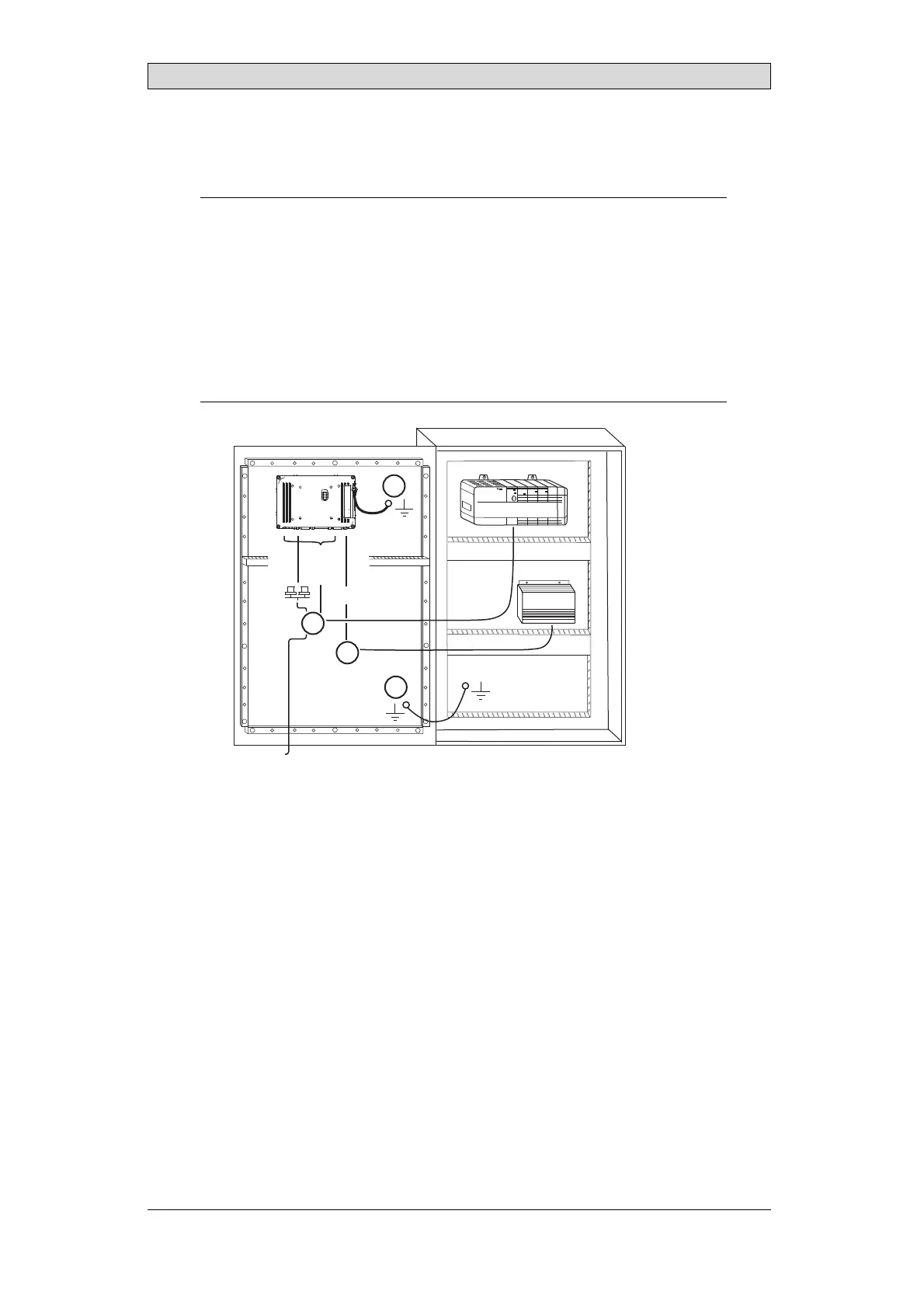
Connect the cables in the specified order, according to the drawing and steps
below.
Caution:
• Theoperatorpanelmustbebroughttoambienttemperaturebeforeitisstarted
up. Ifcondensationforms,ensurethattheoperatorpanelisd rybeforeconnecting
ittoth epoweroutlet.
• Ensurethattheoperatorpanelandthecontrollersystemhavethesameelectrical
grounding(referencevoltagelevel),otherwiseerrorsincommunicationmay
occur.
• Ensurethatthevoltageandpolarityo fthepowersou rceiscor rect.
• Separatehighvoltagecablesfromsignalandsupplycables.
• Shieldedcommunicationcablesarerecommended.
24V DC
RS232/
RS422/
RS485
24V DC
A
D
Controller
Power
B
Ethernet
C
The image is illustrative only and may differ slightly from the actual panel.
– Connect cable A.
– Connect cable B, using 14-20 AWG (2.08–0.52 mm
2
), 180–220 N-cm
torque.
– Connect cable C.
– Connect cable D. The recommended cross-section of th e cable is 1.5
mm
2
.
7.
Carefully remove the protective film over the operator panel display, take care
to avoid static electricity that could damage the panel.
3.2.1 ConnectionstotheController
For information about the cables to be used when connecting the operator panel to
the controller, please refer to the help file for the driver in question.
BeijerElectronics, MAEN330
9