20
9. ACCESSORIES
9.1 Units of measurement & instrument
identification.
New indicators are supplied with a printed scale
card showing the units of measurement and tag
information specified when the instrument was
ordered. If this information was not supplied a
blank scale card will be supplied which can easily
be marked on-site with a dry transfer or a
permanent marker.
Custom printed scale cards are available as
accessories and may be easily fitted as shown in
section 5.6 of this manual.
All models can also be supplied with a blank or
custom laser engraved stainless steel legend plate
- see Figs 5a and 5b. The plate, which after
installation is visable from the front of the
instrument, is supplied loose with two fixing screws
for securing it to the rear of the instrument's back-
box. This plate can typically accommodate:
1 row of 5 alphanumeric characters 10mm high
or 1 row of 6 alphanumeric characters 7mm high
or 2 rows of 10 alphanumeric characters 5mm high
9.2 Display backlight
All models can be supplied with a factory fitted
backlight that may be loop or separately powered.
When loop powered the backlight produces green
background illumination enabling the display to be
read at night or in poor lighting conditions. No
additional power supply, intrinsic safety interface or
field wiring are required, but the indicator voltage
drop is increased. When separately powered the
backlight is brighter, but an additional intrinsic
safety interface and field wiring are required.
Fig 10 Terminals for optional backlight
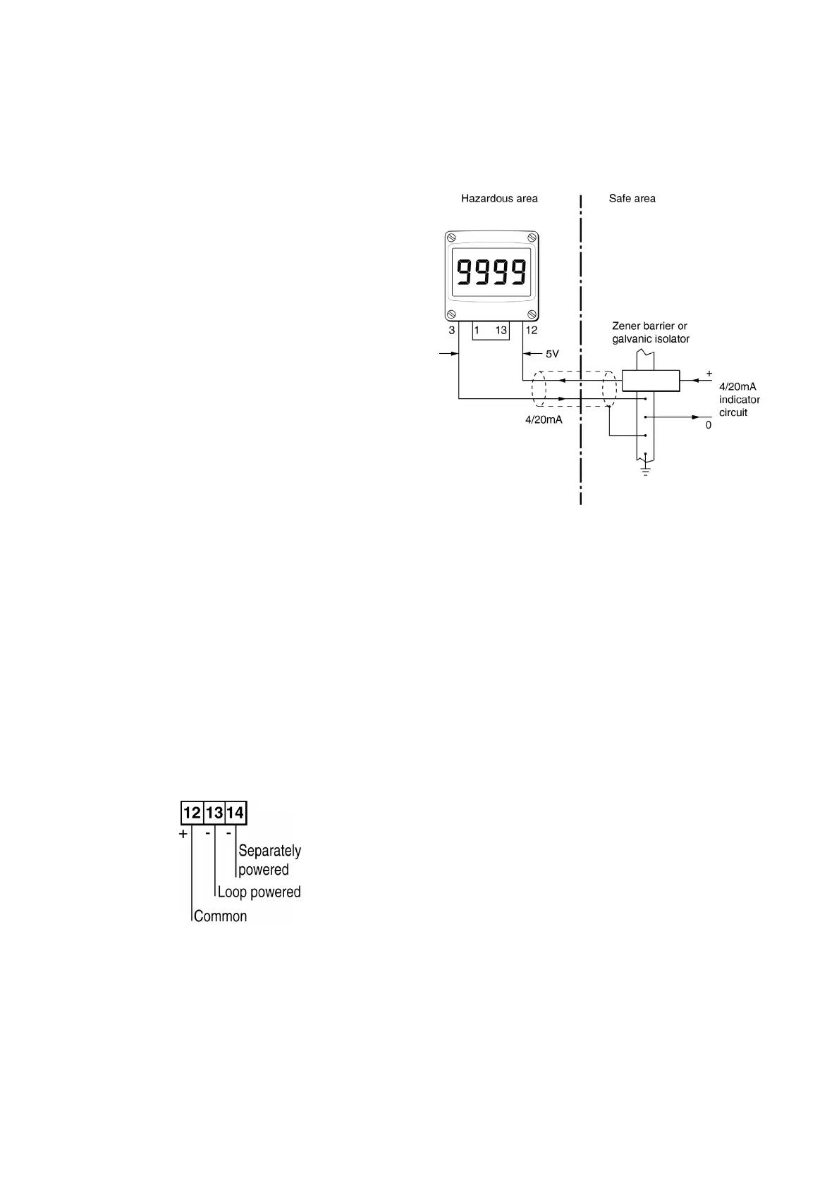
9.2.1 Loop powering the backlight
The backlight is loop powered by connecting it in
series with the indicator’s 4/20mA input as shown
in Fig 11, which increases the maximum indicator
voltage drop from 1.2 to 5V.
Fig 11 Backlight loop powered
The input intrinsic safety parameters of the
combined indicator and backlight are the same as
for the indicator alone. The EC-Type Examination
Certificate states that for intrinsic safety
considerations, under fault conditions the output
voltage, current and power of the combined
indicator and backlight terminals 12 & 3 will not
exceed those specified by clause 5.7 of
EN 60079-11 for simple apparatus,which
simplifies system design and documentation.
Providing the increased voltage drop can be
tolerated the intrinsic safety and system design
described in sections 3 and 4 of this manual
remain valid with the backlight loop powered.