27
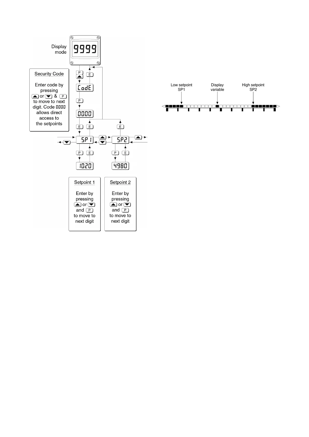
Fig 17 Setpoint adjustment from the display mode
To adjust an alarm setpoint select 5P1 or 5P2 and
press ( which will reveal the current setting.
Each digit of the setpoint may be adjusted using
the & and * push buttons, and the ( button to
move control to the next digit. When the required
setpoint has been entered, pressing ) will return
the display to the 5P1 or 5P2 prompt from which the
other setpoint may be selected, or the indicator
may be returned to the display mode by pressing
) again.
Note: With the indicator in the display mode, direct
access to the alarm setpoints is only available
when the AC5P menu is enabled - see section
9.3.12
9.3.14 Displaying setpoints on BA324G and
BA324G-SS bargraph
One of the selectable bargraph formats Alr5P
allows a low or a high setpoint plus the displayed
value to be represented, or a low and a high
setpoint plus the displayed value to be represented
by the bargraph as shown in Fig 18.
Fig 18 Displayed value and setpoints on bargraph
The bargraph area below the low alarm setpoint
and the area above the high alarm setpoint are
activated. The displayed variable is represented
by an activated bar which moves between these
low and high alarm setpoints.
When the activated bar representing the displayed
variable is adjacent to the area representing the
low or high alarm setpoints, the bar flashes.
When a displayed variable equals the low or high
alarm the complete bargraph representing the
activated alarm flashes irrespective of whether the
alarm output has been delayed or cleared.
For this function to operate 5P1 must be
conditioned as a low alarm and 5P2 as a high
alarm; 5P1 must always be less than 5P2.
Incorrect configuration is shown by a flashing
bargraph scale with no activated bars.