7
5. INSTALLATION
5.1 Location
BA304G and BA324G indicators have a GRP
enclosure and BA304G-SS and BA324G-SS
indicators have a 316 stainless steel enclosure.
Both provide IP66 ingress protection after a 7J
impact and have a thick armoured window which
will withstand a 4J impact. They are suitable for
exterior mounting in most industrial on-shore and
off-shore installations.
The indicators should be positioned where the
display is not in continuous direct sunlight. Special
conditions apply for Zone 0 installations, see
section 3.2.
Field wiring terminals are located on the rear of the
indicator assembly as shown in Fig 5c. Indicator
terminals 2 and 4 are internally joined and may be
used for linking the return 4/20mA wire - see
Fig 5c.
The indicators are surface mounting, but may be
pipe mounted using one of the accessory kits
described in section 9.4 or panel mounted as
described in section 9.5.
5.2 GRP models
BA304G and BA324G
The GRP models are fitted with a bonding plate to
ensure electrical continuity between the two
conduit or cable entries. The bonding plate may be
mounted on the inside or outside of the enclosure
and includes an M4 earth stud. If the carbon
loaded GRP enclosure is not bolted to an earthed
post or structure, this earth stud should be
connected to the plant potential equalising
conductor.
An insulated M4 stud is provided in the bottom
right hand corner of the GRP back-box for
interconnecting cable screens.
If field wiring is to be terminated prior to the
installation of the indicator assembly, the GRP
models, BA304G and BA324G, can be supplied
with an optional back-box terminal assembly,
which includes a 4/20mA continuity diode. See
section 9.6 of this manual. This option is not
available for the stainless steel models,
5.3 Stainless steel models
BA304G-SS and BA324G-SS
The stainless steel models have an earthing
terminal in the lower left had side of the back-box.
If the stainless steel enclosure is not bolted to an
earthed post or structure, this earth terminal should
be connected to the plant potential equalising
conductor.
An insulated M4 stud is provided in the bottom
right hand corner of the stainless steel back-box
for interconnecting cable screens.
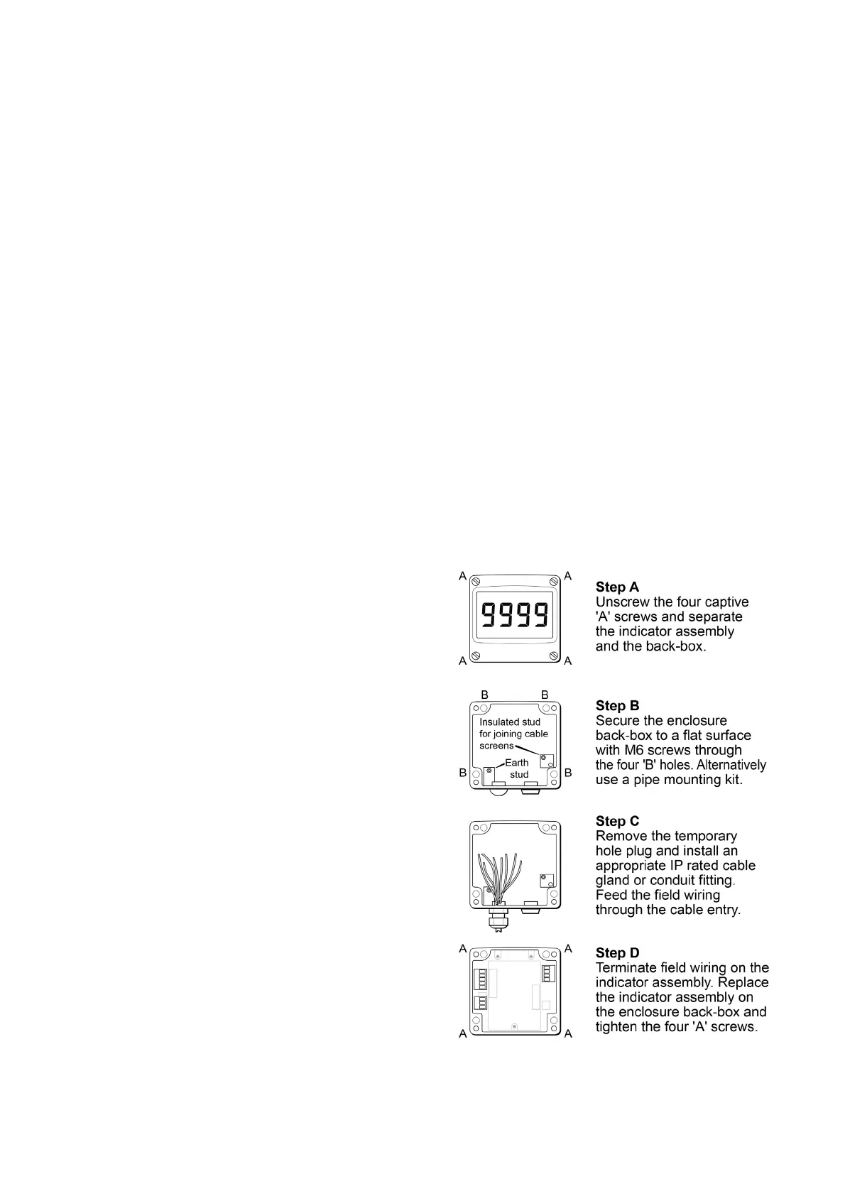
5.4 Installation Procedure
Fig 4 illustrates the instrument installation
procedure for all models.
A. Remove the indicator assembly by
unscrewing the four captive 'A' screws.
B. Mount the enclosure back-box on a flat
surface and secure with screws or bolts
through the four 'B' holes. Alternatively use
one of the pipe or panel mounting kits
described in sections 9.4 and 9.5.
C. Remove the temporary hole plug and install
an appropriate IP and temperature rated
cable gland or conduit fitting. If two entries
are required, the IP66 stopping plug should
be replaced with an appropriate IP and
temperature rated cable gland or conduit
fitting.
D. Connect the field wiring to the terminals as
shown in Fig 5c. Replace the instrument
assembly on the back-box and evenly tighten
the four 'A' screws.
Fig 4 BA304G, BA304G-SS, BA324G and
BA324G-SS installation procedure