3522.5-0000010 OM
245
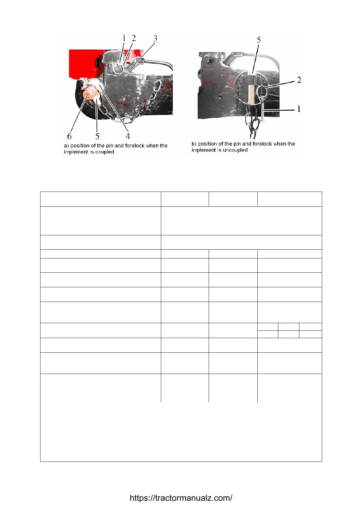
1 – pin; 2 – ring; 3 – gripper handle; 4 – hinged joint; 5 – forelock; 6 – axis of implement.
Figure 5.3.3 а – Locking of the lower drawbars gripper of RLL
Table 5.1 – Basic parameters и coupling dimensions of RLL
“LL-3” “LL-4”
2)
Standard size (configuration)
of the device
(Figure 5.3.1) (Figure 5.3.2)
1 Design features Device consisting of three drawbars (upper one and
two lower ones), articulated by the front ends with
the tractor, and by rear ends with coupling elements
of the implement during operation
2 Purpose To connect (mount) or coupling of mounted, semi-
mounted and semitrailed implements
4)
3 Length of lower drawbars, mm 1060 1118
4 Hinged joint width of the upper (lower)
drawbar, mm
51 (45) 51 (57,5)
5 Diameter of a pin of a rear-end
hinged joint of the upper drawbar, mm
32 32
6 Diameter of pin bore of a rear-end
hinged joint of the lower drawbar, mm
37 50
7. Distance between PTO shaft end
extension face and suspension axis,
mm
675 710
8 Column height
1)
, mm 685 1100
9 Length of the suspension axis along
the collar
1)
, mm
965 1166,5
10 Distance between PTO s
extension face and rear wheel axis
mm
665 665
11 Lifting power of the device, кН
5)
:
а) on the suspension axis;
b) at overhang of 610 mm from the sus-
pension axis
100
65
100
65
_________________________________________________________________________________
1)
Dimension refers to the implement coupling.
2)
Basic variant recommended for the continuous application.
3)
Semitrailed implements are coupled by means of the crossbeam at the ends of the
lower drawbars of rear LL only at towards moving of main traverse, but not reversing.
4)
It is not allowed to give RLL load exceeding loading of tires specified by load-
ing instructions set forth in Table 4.3.
https://tractormanualz.com/


 To Next Page