3522.5-0000010 РЭ
75
Table 2.7 – Relay assignment
Relay desig-
nation
Relay assignament
К1 Radioset (stereo-recorder)
К2 Rear working lights (a pair of inner lights)
К3 Conditioner
К4 Rear working lights (a pair of outer lights)
К5 Front working lights (on the roof)
К6 Not used
К7 Not used
К8 Not used
К9 Not used
К10 Horn
К11 Front working lamps (on handgrip)
К12 Tractor turning indication and emergency indication
К13 Signal from terminal “D” of the alternator to systems of FLL, RLL and
OPU of the HLL control and to electic socket 6 (figure 2.22.2)
К14 Power supply to consumers, staying on when the starter and instru-
ment switch is in position “instruments are on”
К15 Lock of AB remote cutout
К16 Road headlights lower beam
К17 Road headlights upper beam
К18 Parking lights and instrument illumination
К19 Not used
Note – Fuse and relay designation on the switching unit corresponds to fuse and re-
lay designation on tractor electrical diagram in annex D.
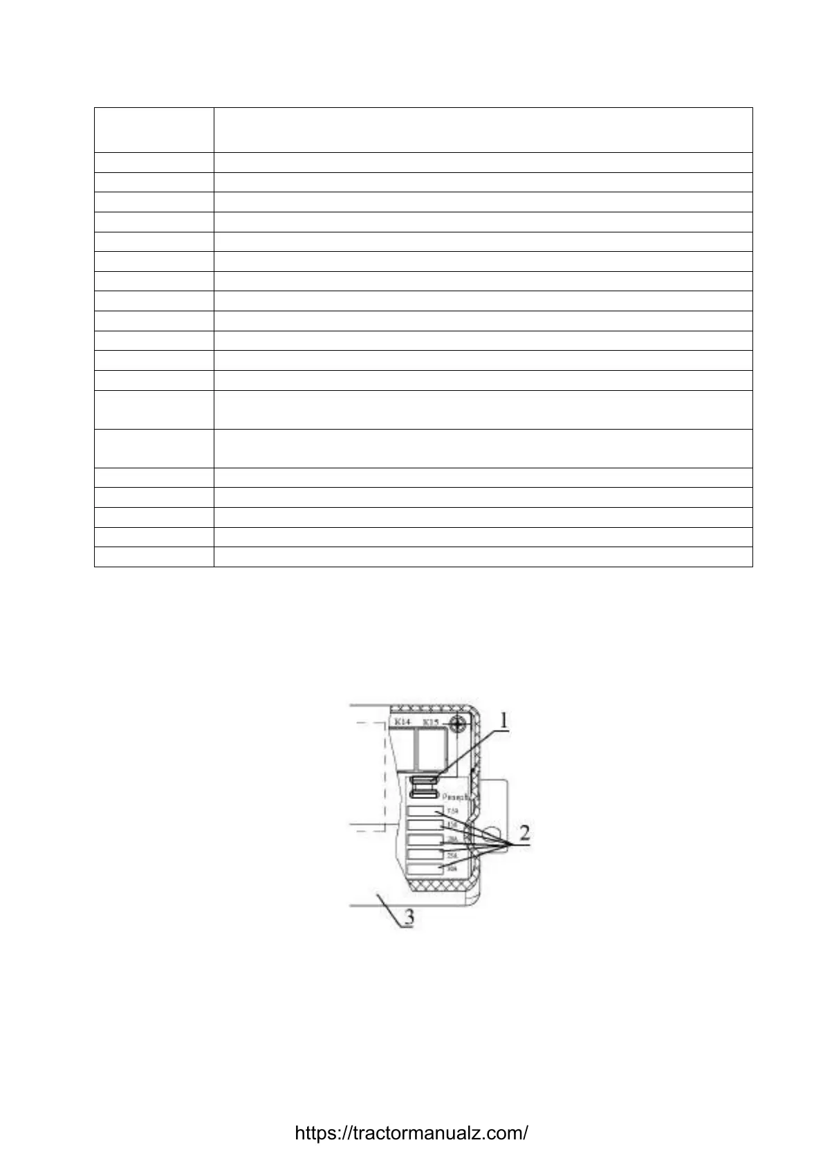
A set of spare fuses 5 (figure 2.18.2), installed on the front panel of the switching
unit, includes spare fuses 2 (figure 2.18.4) with 7,5А, 15А, 20А, 25А, 30А ratings and, for
БКА-7.3722, a fuse removal tool 1. БК-1 is not completed with the fuse removal tool.
1 – fuse removal tool; 2 – spare fuses; 3 – switching unit.
Figure 2.18.4 – Set of spare fuses for the switching unit БКА-7.3722
https://tractormanualz.com/
 Loading...


