V4. 12. 2010
.
Subject to modification
61
Starting point: Actuator in safe position
Procedure
Turn the knob of the auxiliary switch until the
tip of the arrow is pointing to the required
switching position (see right). Example:
Switching point setting = 4 corresponds to
40% angle of rotation.
When the actuator runs to the operating
position (ccw ), the switch knob will also
rotate counter-clockwise (ccw ) and the
auxiliary switch will operate as the tip of the
arrow passes the scale zero (S1–S3 linked).
Auxiliary switch adjustment
Auxiliary switch adjustment for General Damper Actuators
1
1
2
S1
S2 S3
S1
S2 S3
1
0
.2
.4
.6
.8
S1
S2
S3
S1
S2
S3
0
.2
.4
.6
.8
1
R
Auxiliary switch adjustment for Mechanical Fail-Safe Damper Actuators
1. Press the pushbutton, manually operate the universal clamp to
desired switch position.
2. Turn switch pointer to the middle line.
3. When actuator moves clockwise (counter clockwise) to switch
position, switch indicator passes the middle line counter clockwise
(clockwise), the contact between S1 and S3 is disconnected
(connected) and the contact between S1 and S2 is connected
(disconnected).
Note: The switching point should be about 5° from the mechanical
end stops (1 short step on the scale).
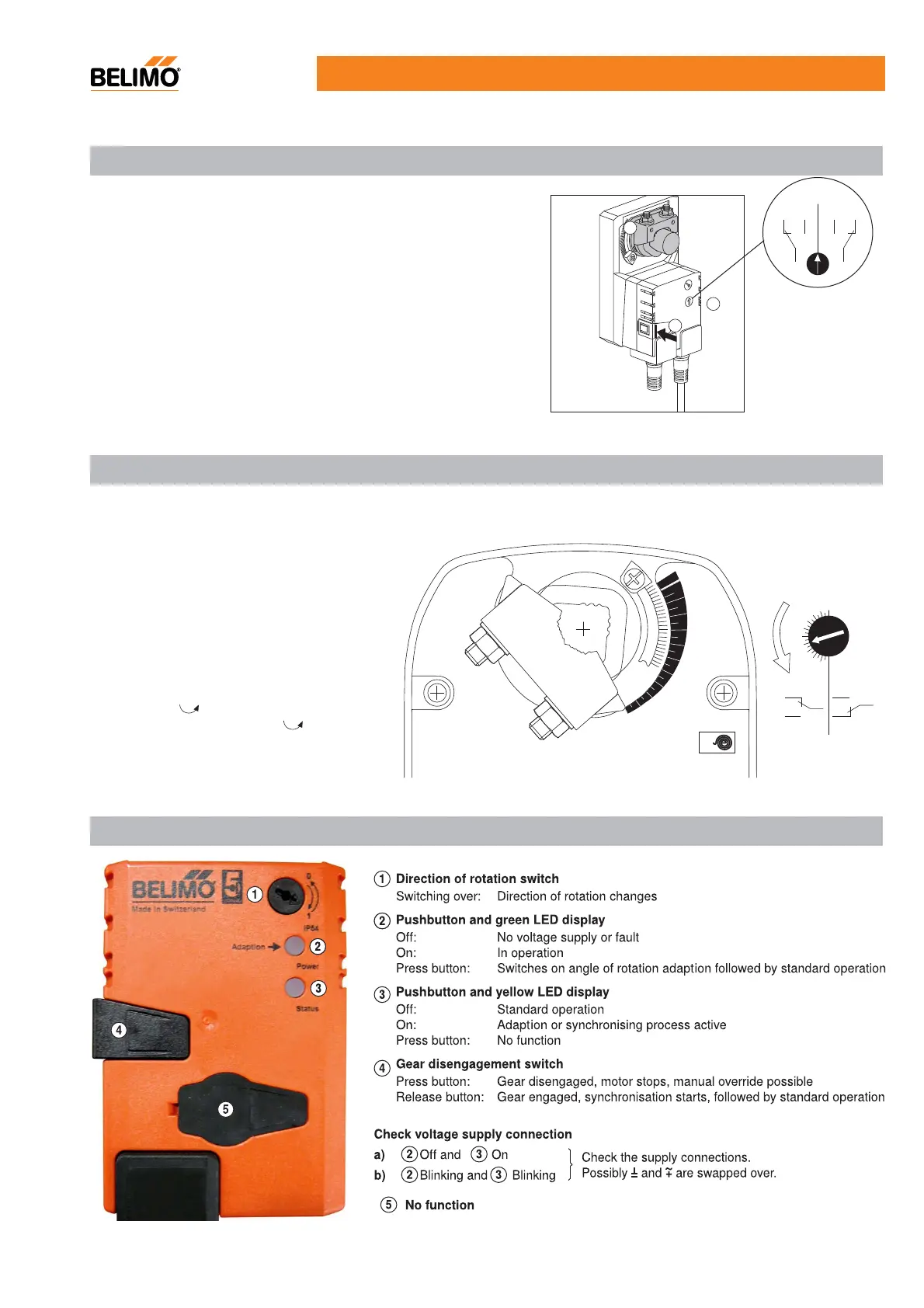
Fast Running Q.. Actuators operating controls and indicators
LF..-S (Mounting side R); NFU-S2, SFU-S2 (Mounting side L)
 Loading...