2
installation
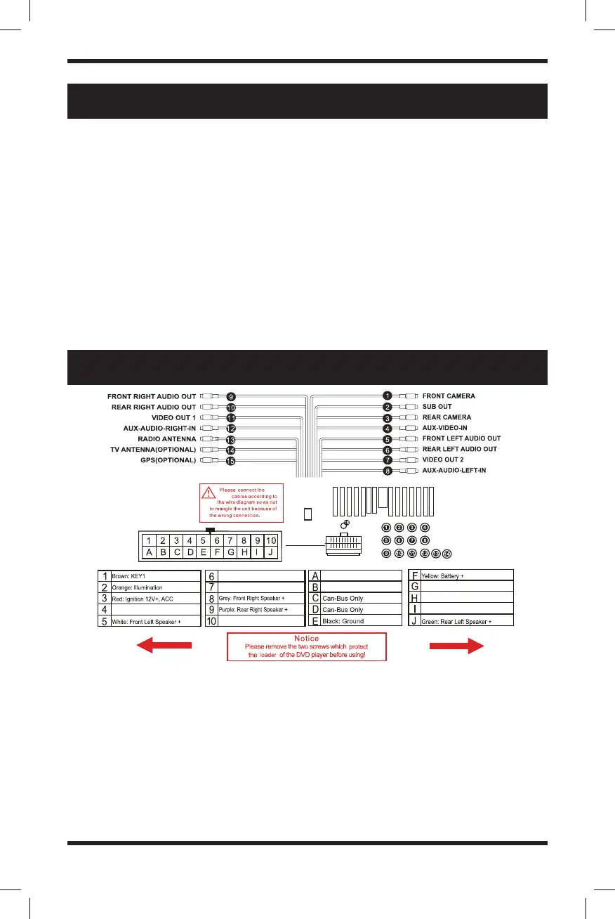
WIRING DIAGRAM
The unit is designed for a 10-16V DC negative ground operation system only. Before
installing the unit, make sure your vehicle is connected to the 10-16V DC negative
ground electrical system.
The negative battery terminal must be disconnected before making connections,
which can reduce damaging the unit from a short circuit.
Be sure to connect the color-coded leads according to the diagram. Incorrect
connections may cause the unit to malfunction or damage the vehicle’s electrical
system.
Be sure the connect the speaker (-) leads to the speaker (-) terminal. Never connect
the left and right channel speaker cables to each other or to the vehicle body. Do
not block vents or radiator panels. Blocking them will cause heat to build up inside
and may result in fire.
1. Brown: KEY1
2. Orange: Illumination +
3. Red: Ignition 12V ACC
4. White/Black: Front Left Speaker -
5. White: Front Left Speaker +
6. Pink: Parking Brake
7. Grey/Black: Front Right Speaker -
8. Grey: Front Right Speaker +
9. Purple: Rear Right Speaker +
10. Purple/Black: Rear Right Speaker -
A. Brown/Black: KEY2
B. Blue/Black: IR
C. Can-Bus Only
D. Can-Bus Only
E. Black: Ground
F. Yellow: Battery +
G. Blue: Auto Antenna/Remote +
H. Orange/Black: Reverse Input
I. Green/Black: Rear Left Speaker -
J. Green: Rear Left Speaker +
(
OPTIONAL
)
Blue: Auto Antenna/Remote +
Pink: Parking Brake
Orange/Black: Reverse Input
Brown/Black: KEY2
Blue/Black: IR
Grey/Black: Front Right Speaker -
Purple/Black: Rear Right Speaker -
White/Black: Front Left Speaker -
Green/Black: Rear Left Speaker -