1
The Procombi A comprises a range of high-efficiency
combination boilers with outputs to DHW of 28kW, 32kW,
and 36kW respectively. These appliances – by design
– incorporate electronic ignition, circulating pump,
expansion vessel, safety valve, pressure gauge and
automatic by-pass.
The Procombi range is produced as room sealed, category
II2H3P appliances, suitable for internal wall mounting
applications only. Each appliance is provided with a fan
powered flue outlet with an annular co-axial combustion air
intake that can be rotated – horizontally – through 360
degrees for various horizontal or vertical applications.
The Procombi A is approved for use with C13 & C33 type
flue applications.
These appliances are designed for use with a sealed
system only; consequently they are not intended for use
on open vented systems.
This booklet is an integral part of the appliance. It is
therefore necessary to ensure that the booklet is handed
to the person responsible for the property in which the
appliance is located/installed. A replacement copy can
be obtained from customer services.
INTRODUCTION
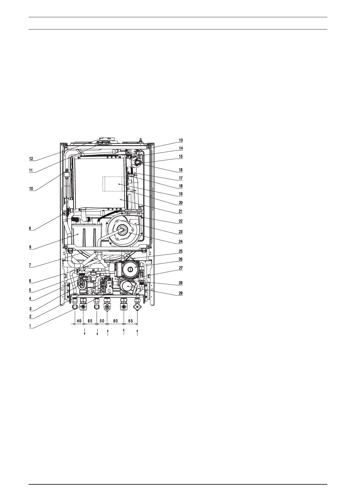
fig. 1
General layout (fig. 1)
1 Gas valve
2 Modulator coil
3 Discharge valve
4 Pressure switch
5 Domestic hot water sensor
6 Safety valve
7 Expansion vessel
8 Condense trap
9 Return sensor
10 Fumes thermostat
11 Flue gas analysis test point
12 Flue outlet & air intake
13 Ignition transformer
14 Top AAV
15 Flow sensor
16 High limit thermostat
17 Sensing Electrode
18 Spark Electrode
19 Cylindric Burner
20 Condensate level sensor
21 Main heat exchanger
22 Top AAV pipe
23 Fan assembly
24 Mixer
25 Bottom auto air vent (AAV)
26 Pump
27 DHW flow switch
28 Domestic hot water heat exchanger
29 Three porte valve actuator
F Heating flow connection
O Hot water outlet
G Gas connection
R Heating return connection
I Cold water inlet
G
O
I
R
F