6 720 611 447 GB (03.11)
Installation
15
Fixing the appliance
B Fit the washers onto the gas and water connections.
B Lift the boiler onto the wall-mounting frame. The lugs
pass through the rectangular holes in the boiler back
panel.
B Take care not to disturb the washers on the connec-
tions.
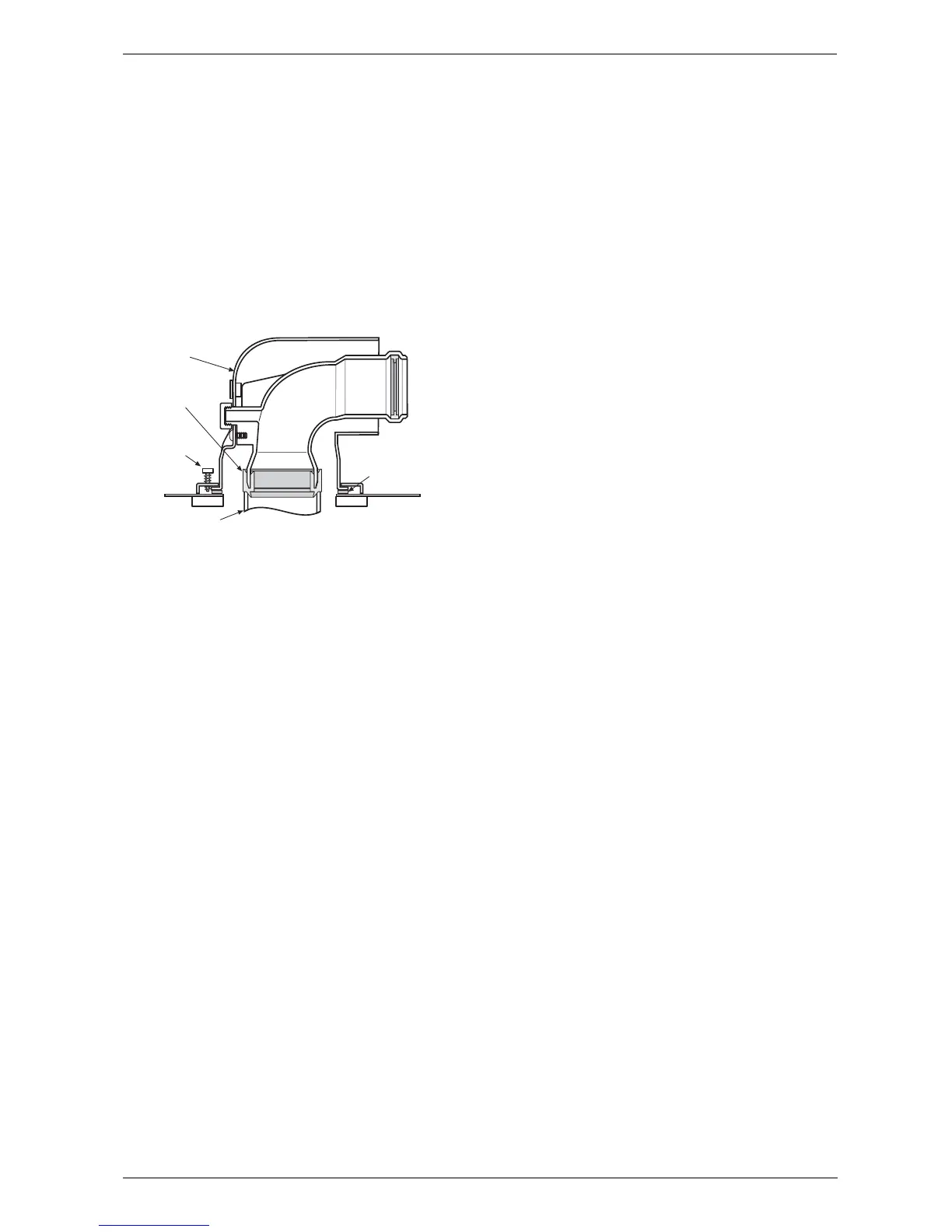
Connecting the flue duct
B Fit flue duct connector onto boiler flue socket.
B Secure with the screws supplied.
Fig. 14
B For remaining installation of flue assembly, refer to
the relevant installation instructions.
3.8 Checking the connections
Water connections
B Check that the O-rings or seals are in place before
tightening the connection.
B Turn on the service valves for central heating flow
and return and fill the heating system through a
WRAS approved filling loop.
B Check all seals and unions for leaks (testing pressure
max. 3.0 bar as indicated by pressure gauge).
B Turn on cold water service cock and fill hot water sys-
tem (testing pressure max. 10 bar).
B Check all connections for leaks.
Gas supply pipe
B Check that the seal is in place before tightening the
connection.
B Turn off gas cock to protect gas valve against dam-
age from excessive pressure.
B Check gas supply pipe.
B Release the pressure on the gas supply pipe.
3.9 Flue Systems
The only flue systems that may be used are those sup-
plied with the boiler.
The flue system must be installed in accordance with
the requirements of BS5440:1.
Standard 100 mm flue system
The standard concentric flue system provides for a hor-
izontal length of up to 4m (3.5m RD542i). Full instruc-
tions for fitting this flue are in Subsection 3.9.2
“Installation of the flue”.
Alternative 125 mm diameter flue systems
Installation instructions for the alternative flue systems
are sent with the appropriate flue kit.
Systems are available for a maximum horizontal length
of 13m (RD532i),10m (RD537i/542i).
A vertical flue system up to a height of 13.7 m (RD532i)
and10.7 m (RD537i/542i) is available.
45° and 90° flue bends can be used with a reduction in
flue length of 2 m for each 90° bend and 1 m for each
45° bend used.
IMPORTANT: Any horizontal flue system fitted to a
condensing boiler must incline from the appliance at an
angle of 3° (30 mm per metre length) to prevent con-
densate dripping from the flue terminal.
Note, the standard 100mm horizontal flue requires only
a 0.5° incline from the boiler as the inner exhaust pipe is
inclined at 2.5° inside the outer pipe.
This means that the clearance above the appli-
ance must be increased to match the duct length.
Refer to fig. 1 on page 5.
Retaining
Screw
Flue Turret to
Boiler Sealing
Gasket
Flue Turret
6 720 610 599 - 01.TD
Appliance
Flue Socket
Flue seal