6 720 611 447 GB (03.11)
Electrical connections
21
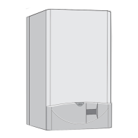
B Cut cable grommet to diameter of cable.
Fig. 27
B Feed cable through cable grommet and connect the
mains supply cable, see fig. 28.
B Secure cable in cable grommet by means of cable
grip.
Fig. 28
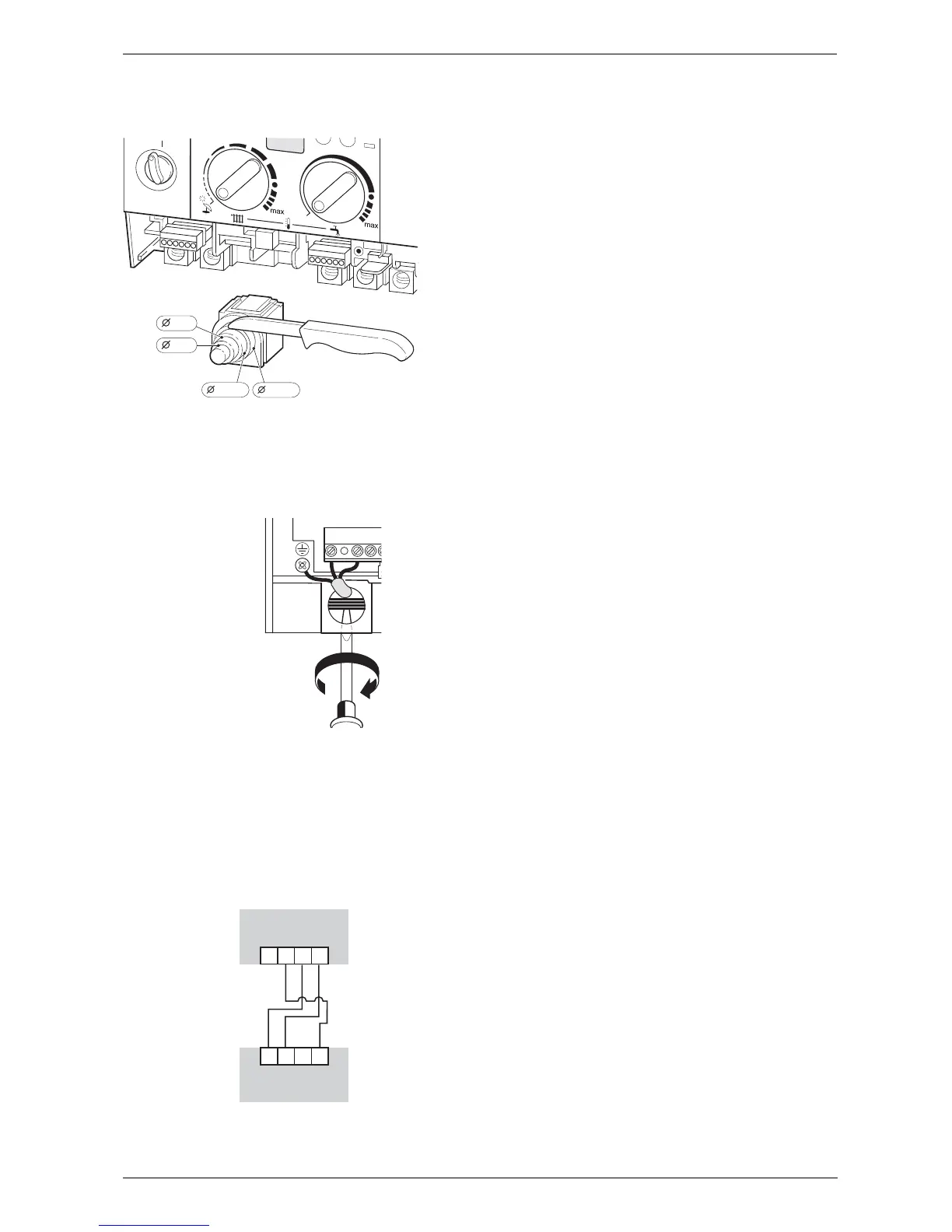
4.2 Connecting a TR2 Room Thermo-
stat (accessory)
Connect the TR2 to terminals 3, 4 and F beneath the
Text display (page 8, fig. 4, item 422) using a minimum
1mm cable to avoid incresing resistance between the
terminals, see Fig. 29
Fig. 29
4.3 Mains Voltage external controls
connections
Externally wired controls are not required; the boiler has
a built-in text display programmer and frost protection.
The TR2 room thermostat provides additional frost pro-
tection and compliance to Part L of the Building Regu-
lations.
0
1
2
3
4
5
E
6 720 610 332-12.1R
13-14
10-12
8-9
5-7
N
S
LN