6 720 611 447 GB (03.11)
34
Converting the appliance to different gas types
Fig. 43
B Press or to select Min.
B Measure the CO
2
level.
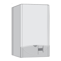
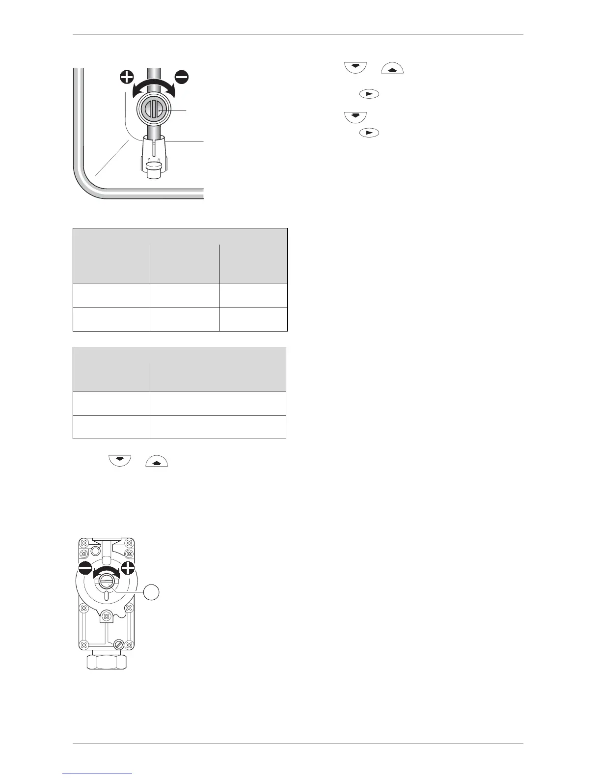
B Remove the seal from the gas valve adjusting
screw (64) and adjust the CO
2
level to the figure
given in Table 15 for min. rated heat output. Refer to
fig. 44.
Fig. 44
B Recheck the levels at min. and max. rated heat output
and re-adjust if necessary.
B Press or until the display shows
normal.
B Press the button. The text display shows
Store settings.
B Press to select yes.
B Press the button.
B Remove testing probe from the flue gas testing
point (234) and refit sealing plug.
B Re-seal gas valve adjusting screw and gas flow
restrictor.
B Replace the outer case by locating it on the top lugs
and pushing backwards until the bottom clips are
fully engaged. Check that the case is properly
aligned with facia. Refer to fig. 13.
B Secure by replacing the screw at the bottom left.
Refer to fig. 13.
RD532i
Gas Type
CO
2
reading
at max. rated
heat output
CO
2
reading
at min. rated
heat output
Natural gas type
G20
9.2 % 8.8 %
LPG G31
(propane)
10.8 % 10.5 %
Table 15
RD537i/542i
Gas Type
CO
2
reading at max. and min.
rated heat output
Natural gas type
G20
9.2 %
LPG G31
(propane)
10. 8 %
Table 16
63
6 720 610 332-64.1R
6