Do you have a question about the Bendix/King KY 197 and is the answer not in the manual?
Overview of the manual's content and scope for the VHF transceivers.
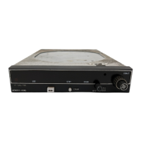
Details the physical and functional aspects of the KY 196/196E/197/197E transceiver.
Lists detailed specifications, compliance, and performance data for the units.
Itemizes the components included with the transceiver and its installation kit.
Lists essential external components needed for operation.
Outlines FCC licensing needs for operating the transmitter.
Provides general suggestions and factors to consider before installing the transceiver.
Details procedures for safely unpacking and checking the unit for damage.
Covers general guidelines and considerations for installing the transceiver.
Explains the importance of cooling for unit reliability.
Describes how to install the mounting rack for the transceiver.
Provides recommendations for proper installation of the COMM antenna.
Details the process of assembling connectors for the wiring harness.
Describes the final steps for securing the unit into its mounting rack.
Outlines procedures for verifying proper installation and performance post-installation.
Explains how to power on and use the transceiver's basic functions.
Describes the procedure for powering the transceiver on.
Explains the 'T' indicator during transmission.
Details the different operating modes like Frequency, Program, and Channel.
Describes how to transfer frequencies using a remote switch.
Explains using a remote switch to cycle through memory channels.
| Type | VHF Communication Transceiver |
|---|---|
| Channel Spacing | 25 kHz |
| Number of Channels | 760 |
| Modulation | AM |
| Weight | 2.5 lbs (1.13 kg) |
| Operating Voltage | 13.75 V DC |
| Channels | 760 |
| Frequency Range | 118.000 MHz to 136.975 MHz |
| Power Output | 10 W |
| Transmitter Power Output | 10 Watts (Carrier Power) |