KY 196
064-1019-00
Non-Glare lens
KY 196E
064-1019-01
Non-Glare lens
KY 196
064-1019-02
Standard lens
KY 196
064-1019-05
Non-Glare lens,
Memory
Channels
KY 196E
064-1019-06
Non-Glare lens,
Memory
Channels
KY 196
064-1019-07
Standard lens,
Memory
Channels
KY 196
064-1019-10
Non-Glare lens,
Memory
Channels,
Remote
Transfer/Inc
KY 196E
064-1019-11
Non-Glare lens,
lIo1emory
Channels,
Remote
Transfer/Inc
KY 196
064-1019-12
Standard lens,
Memory
Channels,
Remote
Transfer/Inc
KY 197
064-1021-00
Non-Glare
lens
KY 197E
064-1021-01
Non-Glare
Lens
KY 197
064-1021-05
Non-Glare
lens,
Memory Channels
KY 197E
064-1021-06
Non-Glare
lens,
Memory
Channels
KY 197
064-1021-10
Non-Glare
lens,
Memory
Channels,
Remote
Transfer/Inc
KY 197E
064-1021-11
Non-Glare
lens,
Memory
Channels,
Remote
Transfer/Inc
1.2
EQUIPMENT
DESCRIPTION
KING
KY 196/196E/KY 197/197E
VHF COMMUNICATIONS TRANSCEIVER
SECTION I
GENERAL INFORMATION
1.1 INTRODUCTION
This manual contains information relative to the physical, mechanical, and electrical characteristics of
the King Radio Corporation Silver Crown KY 196/196E/197/197E 720 channel VHF communications transceivers.
Installation and operating procedures are also included. Information relative to t"e
maintenance,
alignment, and procurement of replacement parts may be found in KY 196/196E/197/197E Maintenance/Overhaul
Manual.
The units covered are as follows:
NOTE
All KY 196/196E RADIOS ARE 27.5 VDC, All KY 197/197E RADIOS ARE
13.75 VDC.
The KY 196/196E/197/197E transceiver is a TSO'd 720 channel communications transceiver and is desiqned to
provide two-w::lYvoice communication within the frequency range of
11~.OOOMHz
to B,).975MHz in ~5KHz
increments.
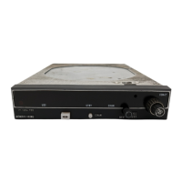
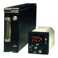
The KY 196/196E/197/197E is a panel mounted unit. Connections to the unit are made throuqh a 20 pin
Molex printed circuit board edge connector and a BNC coax connector at the rear of t"e unit.
ElectricaLLy, the KY 196/196E/197/197E consists of four sections: receiver, transmitter, frequency
synthesizer, and gas-discharge display circuitry. The only difference between the KY 196/197 and I<Y
196E/197E lies in their selectivity specifications (see Section 1.3). The only difference between the KY
196/196E and KY 197/197E is thei r rated t ransmi tter power out out and power requi r~ments (see Secti on
1.3) .
The KY 196/196E (-aS, -06, -07) and the KY 197/197E (-OS, -06) "ave the capability of oreproqra~minq UP
to nine memory channel frequencies for later recall. Channel frequency information is stored in ::I
non-volatile earom memory so that when the radio is turned off and then back on, channel information is
retained.
The KY 196/196E (-10, -11, -12) and the KY 197/197E (-10, -11) have the capability of remote transfer of
use and standby frequencies and the remote recall of channel frequency information.
Rev. 3, September, 1983
IM0035-3
Paqe 1-1