3
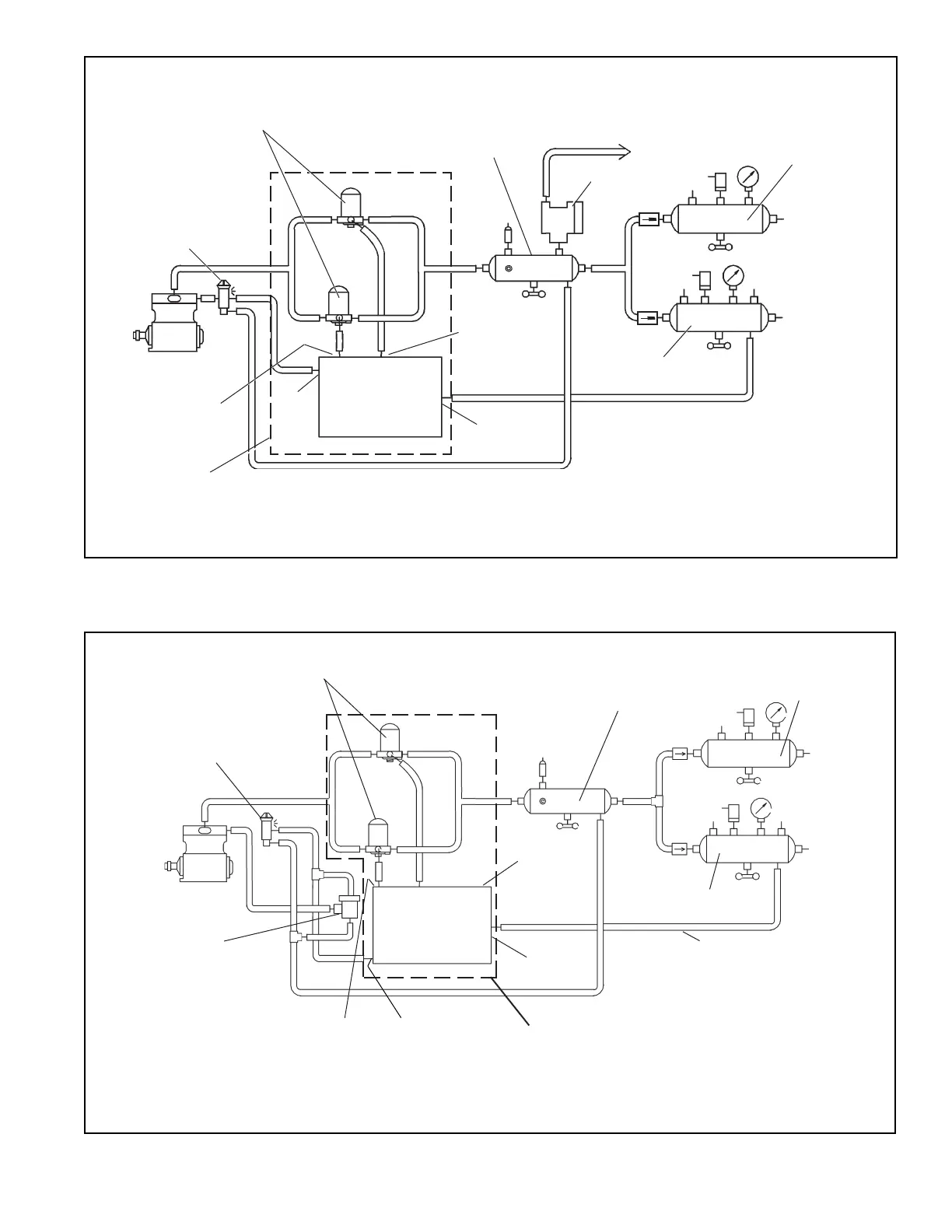
FIGURE 2 - BENDIX
®
EVERFLOW
®
AIR DRYER ASSEMBLY INSTALLATION
Bendix
®
EverFlow
®
Control Module
Compressor
Governor
1/4”
1/4”
RES
1
GOV
CON
4
Control
Dryer
#1
Control
Dryer #2
Supply
Reservoir
Primary
Reservoir
Secondary
Reservoir
Pressure
Protection
Valve
TO HIGH
AIR USE
ACCESSORIES
FIGURE 3 - BENDIX
®
EVERFLOW
®
AIR DRYER ASSEMBLY INSTALLATION WITH A BENDIX
®
DURAFLO 596
™
COMPRESSOR
Bendix
EverFlow
Control Module
Bendix
®
Durao 596
™
Compressor
Governor
1/4”
1/4”
RES
1
Control
Dryer #2
Control
Dryer #1
E
D
S
D
S
C
D
S
C
D
S
C
GOV
CON
4
D
S
C
D
S
C
E
D
S
Bendix
®
SV-1
™
Synchro Valve
Bendix
®
EverFlow
®
Air Dryer
Assembly
Bendix
EverFlow
Air Dryer Assembly
3/8”
Bendix AD-IP, AD-IS or
AD-9 Air Dryer
Supply
Reservoir
Primary
Reservoir
Secondary
Reservoir
Bendix
®
AD-IP
®
, AD-IS
®
or AD-9
®
Air Dryer
This schematic is a general guideline. For specic applications or questions
contact the Bendix TechTeam at 1-800-AIR-BRAKE (1-800-247-2725).
This schematic is a general guideline. For specic applications or questions
contact the Bendix TechTeam at 1-800-AIR-BRAKE (1-800-247-2725).