4
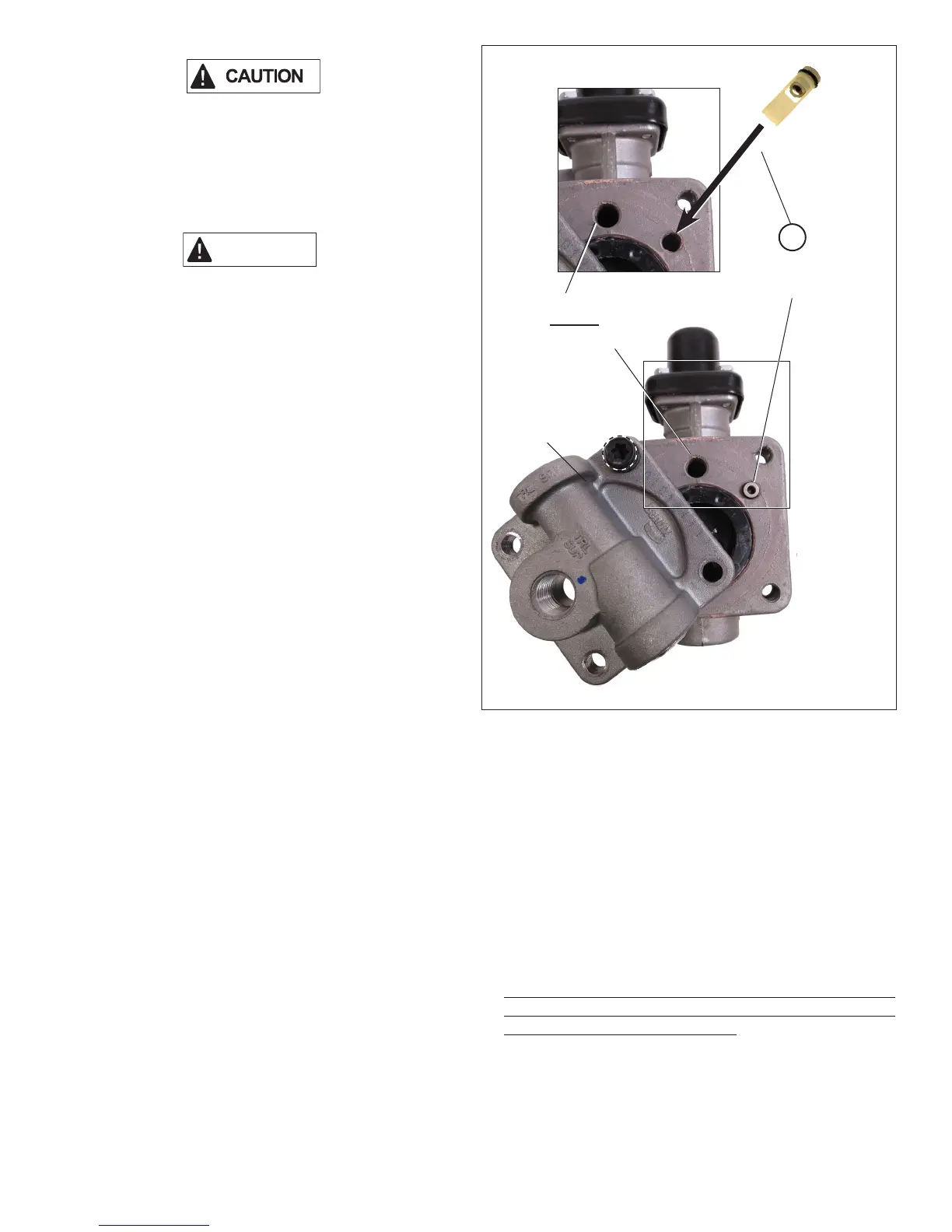
Figure 8 – Check Valve Cartridge Installation
A
Control
Piston
Cover
ASSEMBLY
1. Ensure that the check valve cartridge (1) is intact as shown
in Figure 8.
2. Holding the larger diameter (o-ring end) of the check valve
cartridge (1), insert the pointed end into the air passage.
Push the check valve cartridge (1) in lightly with your nger
until it is ush with the body housing. (Refer to Figure 8.)
AT TENTION
THE CHECK VALVE CARTRIDGE (1) WILL FIT SNUGLY
INTO THE CORRECT AIR PASSAGE. DO NOT INSERT
THE CHECK VALVE CARTRIDGE (1) INTO THE LARGER
AIR PASSAGE.
3. Rotate the cover back into position and install the three
screws. Torque all four screws in a crossing pattern to
100 in-lbs. (A, C, D then B). (Refer to Figure 3.)
4. Reposition any ttings that may have been moved and
reconnect the air lines.
5. Perform the OPERATIONAL AND LEAKAGE TESTS
detailed below before placing the vehicle back into service.
OPERATIONAL AND LEAKAGE TESTS
This test can be performed by connecting the red trailer
gladhand to a tractor or an external air source. Check the air
source gauge against a gauge known to be accurate before
performing these tests.
1. Block all wheels or hold the vehicle by means other than
the air brakes: drain all pressure from the trailer reservoir.
2. Install a gauge in the trailer reservoir(s). Connect the air
source to the red supply gladhand of the trailer on which
the Bendix
®
SR-5
™
trailer spring brake valve is to be tested.
Build the trailer to full system pressure by placing the tractor
park control valve in the charge position, or by applying
an external air source. Make sure that the spring brake
chambers release before the reservoir starts to ll.
3. When full system pressure is reached – and the spring
brakes are fully released – apply a soap solution to the
control piston cover and ttings that were removed during
the repair. A one inch bubble in ve seconds is permissible.
4. Place the trailer air supply valve in the exhaust position,
or disconnect the external air source. The spring brakes
should apply. This will be evident by a full exhausting of
chamber pressure at the SR-5 valve exhaust port.
If the repair was completed correctly, the park brakes should
be set, and the reservoir pressure should hold steady with
no decay. If the valve does not perform properly, repeat the
installation procedure and retest.
5. Drain the reservoirs and remove the gauge that was
installed in the trailer reservoir(s) for testing purposes.
Reinstall the tting that was removed. Recharge the trailer
air system and check for leaks using a soap solution. A one
inch bubble in ve seconds is permissible.
6. For identication purposes, secure the green tie wrap (2)
through the identication hole located on the valve body.
(Refer to Figure 2.)
7. Included in this kit is an SR-5 decal (5) that can be placed
on the trailer upon completion of the valve installation.
The installation of this decal is not required; however, it
may be helpful for quick identication of the trailers that
have been serviced per the recall. Space is provided for
the technician's name and date of installation.
1
Check Valve
Cartridge
This port must remain
open. Do not install
the check valve here.