SP-7XE/F Full-Rise Scissor Lift 22 P/N 5900010 — Rev. B3 — September 2023
Create Chalk Line Guides SP-7XE Only
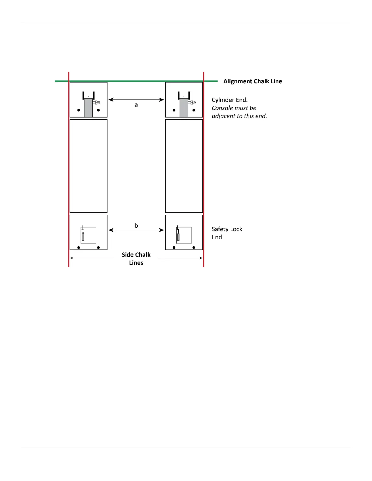
Create Chalk Line Guides to make sure the Frames are parallel and in the desired location.
The following drawing shows the Alignment Chalk Lines to create for your Lift.
To add Chalk Line Guides:
1. Decide where the Lift is to be located.
2. Refer to the figure above. Create an Alignment Chalk Line for one end of the SP-7XE.
Make the Alignment Chalk Line longer than the Overall Width and the space between them.
3. Create two additional Side Chalk Lines: they need to be perpendicular to the Alignment Chalk Line,
parallel to each other, and the correct distance apart (38 in. to 44 in. / 965 mm to 1,118 mm plus
the width of the two Frames, 44 in. / 1,118 mm).
4. Move each Frame into position, into the corners created by the four Chalk Lines.
NOTICE The Hydraulic Cylinder ends of both Frames must be positioned adjacent to the
Console.
5. Measure the distance between the two Frames at points a and b; they need to be the same
distance apart at both ends.
Important: If a and b are not the same, adjust the position of the Frames to make them the same;
a and b must be the same distance apart and parallel to each other.
6. When the Frames are in the correct location, move to the next section.