24
9. Grip the shotgun in one hand and with
the other, pull the barrel forwards,
sliding the ring over the magazine
tube until it is fully disassembled.
10. Remove the fore-end-bolt-swivel unit
from the receiver.
11. Separate the swivel unit from the
bolt unit.
12. Pull the ring pin retaining pin out of
the bolt unit, being careful to hold the
unretained ring pin in place, as it
could be pushed out of the bolt by its
spring and fall to the ground.
13. Take the ring pin and its retaining
spring out of the bolt.
14. Take the locking head rotating pin out
of its seat.
15. Slide the locking head from the bolt.
Function test
Whenever the shotgun is reassembled
after cleaning and maintenance, a brief
function test should be conducted be-
fore ring to ensure that all parts and
safeties are assembled correctly and
functioning properly.
Warning: Visually and physically
check the chamber, carrier and maga-
zine to ensure no ammunition is pres-
ent. Always keep the shotgun pointed
in a safe direction.
1. Engage the safety (“ON” position)
and close the bolt by moving the fore-
end fully forward. The bolt should move
smoothly with the swivel.
2. Without activating the bolt release le-
ver, pull the fore-end back. The bolt
should remain locked and not open.
3. Press the bolt release lever. The bolt
should unlock.
4. Move the fore-end all the way back and
then all the way forward. It should move
freely and then lock again in the closed
position.
5. With the safety engaged (“ON” posi-
tion), press the trigger. The hammer
should not drop.
6. Move the safety button to the “re” po-
sition (red ring visible) and pull the trig-
ger. The hammer should drop and the
bolt should unlock.
7. Repeat the bolt, moving the fore-end all
the way back and then all the way for-
ward. Make sure that the bolt locks cor-
rectly. Press the trigger. The hammer
should drop. Open the bolt completely.
Warning: Follow all safety instructions
regarding engaging the safety (“ON”
position) and keeping the muzzle
pointed in a safe direction.
ACCESSORIES AND ADJUST-
MENTS
▀
Drop and cast adjustment
Before carrying out any type of inter-
vention on the shotgun, always make
sure that the chamber and magazine
are completely empty!
(Carefully read the instructions for loading
and unloading the shotgun).
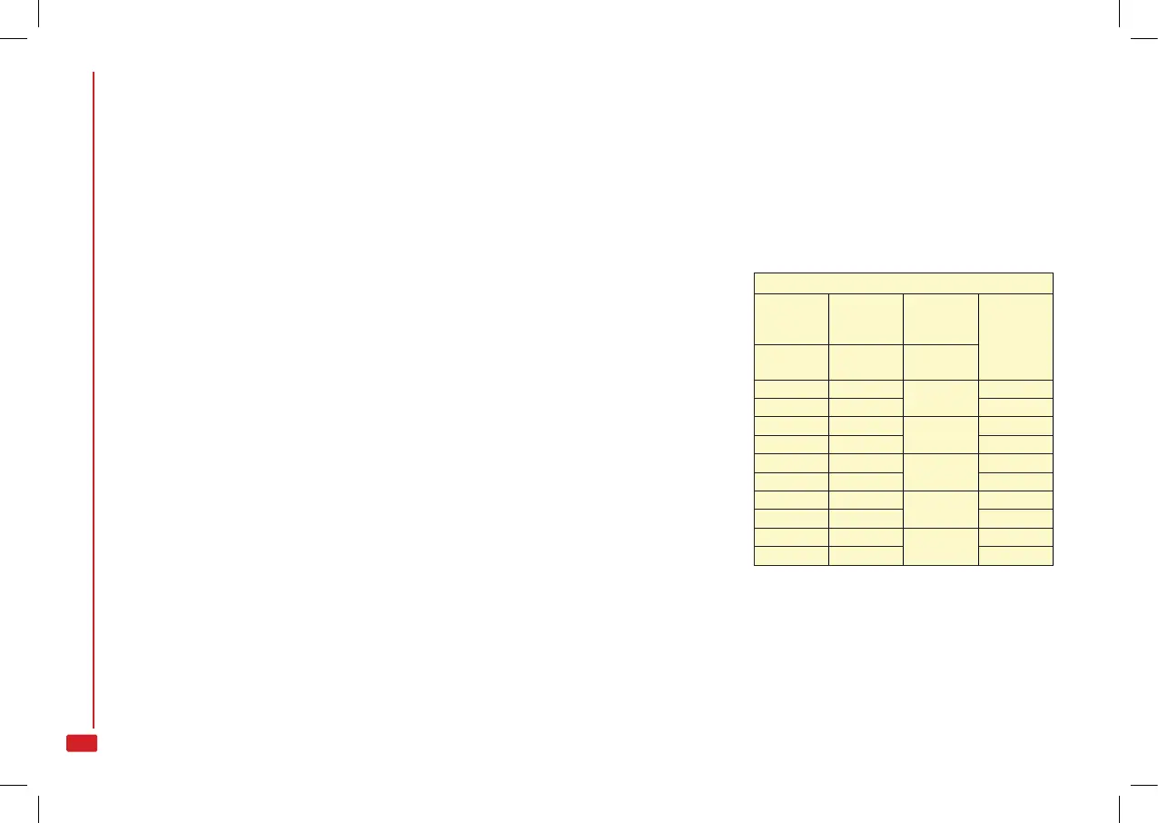
DROP CHANGE TABLE
Cast shim
(plastic)
Stock
locking
plate (steel)
Drop shim
(plastic)
Drop value
at heel
(mm)
Reference
letter
Reference
letter
Reference
letter
DX Z DX
Z
50 ±1 DX
SX Z SX 50 ±1 DX
DX A DX
A
55 ±1 DX
SX A SX 55 ±1 DX
DX B DX
B
60 ±1 DX
SX B SX 60 ±1 DX
DX C DX
C
65 ±1 DX
SX C SX 65 ±1 DX
DX D DX
D
70 ±1 DX
SX D SX 70 ±1 DX
Matching instructions: the drop change
shims and stock locking plates in the kit
are identied by letters. To ensure a cor-
rect drop, always use plates and shims
with the same letter.
E.g.: C - CDX – for a 65-RH drop or C -
CSX – for a 65-LH drop.
DX = Right hand
SX = Left hand