8
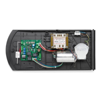
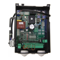
CELL.P control unit with microcontroller
INPUT/OUTPUT FUNCTIONS
Terminals Function Description
1, 2, 3 Power supply Input, 230VAC 50/60Hz
(1-Phase/2-Neutral/GND-Ground connection)
4, 5, 6 Motor Connection to motor:
(MOT-move/COM-Common/MOT-move)
7 LAMP Output, connection to Flashing light: 230 Vac 40W max.
8 SWO Input, OPENING limit switch (Normally Closed contact)
9 SWC Input, CLOSING limit switch (Normally Closed contact)
10 DAS/ PHOT Safety edge or photocell Input
See DIP-SWITCH 3.
TECHNICAL DATA
Control unit power supply
230 Vac
Power supply
230 Vac 50/60 Hz or 115Vac 50/60Hz according to the version
Output supply
1 motore230 Vac
Power maximum motor
1000 W
Output supply accessories
24 Vac, 7W max.
Protection level
IP54
Operating temp.
-20°C / +70°C
WARNINGS
This manual has been especially written to be use by
qualified fitters.
None of the information provide in this manual can be
considered as being of interest for the end users.
Preserve this manual for future needs.
The technician has to furnish all the information rela-
ted to the step by step function, the manual and the
emergency function of the operator, and to deliver the
manual to the final user.
;
Foresee on the supply net an onnipolar switch
or selector with distance of the contacts equal
or superior to 3 mms.
Verify that of the electrical system there is an awry diffe-
rential interrupter and overcurrent protection.
Some typologies of installation require the connection of
the shutter to be link at a conductive mass of the ground
according to the regulations in force.
The electrical installation and the operating logic must
comply with the regulations in force.
The leads fed with different voltages must be physically
separate, or they must be suitably insulated with addi-
tional insulation of at least 1 mm.
The leads must be secured with an additional fixture
near the terminals.
During installation, maintenance and repair, interrupt
the power supply before opening the lid to access the
electrical parts
Check all the connections again before switching on
the power.
The unused N.C. inputs must be bridged.
The descriptions and the present illustrations in this ma-
nual are not binding. Leaving the essential characteristi-
cs of the product unchanged, the manufacturer reserves
himself the right to bring any change of technical, con-
structive or commercial character without undertaking
himself to update the present publication.