13
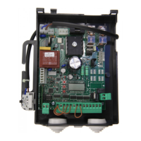
CP.ZED230-E CONTROL UNIT
WIRE DIAGRAM
Wire connections shown in Fig. 1 are described hereunder:
Terminal No. Function Description
1-2 Power supply Input, 230VAC 50Hz (1-Phase/2-Neutral)
3-4 Flashing light Connection of flashing light, 230Vac 40W max.
4-5 Motor light Connection to the courtesy light (230VAC 40+40W max.).
6-7-8 Motor 1/2
Connection to motor 1/2 : (6-speed/7-Com/8-speed)*
Should 2 motors be used, connect the second motor in parallel.
9 COM Common for limit switch and all control inputs.
10 SWO Input, OPEN limit switch (N.C. contact)
11 SWC Input, CLOSE limit switch (N.C. contact)
12 STOP Input, STOP push button (N.C. contact)
13 PHOT
Input, connection to safety devices, N.C. contact
(e.g. Photocells)
14 OPEN Input, OPEN push button (N.O. contact)
15 CLOSE Input, CLOSE push button (N.O. contact)
16 Step-by-Step Input, step-by-step push button (N.O. contact)
17-18 24 Vac Output, power supply of accessories, 24Vac/1A max.
19-20 AUX Normally Open (N.O.) contact, not powered, configurable as SCA/II°CH/PHOTO TEST.
21-22 COSTA
Input, safety edge contact
Resistive edge: Closed “DAS” jumper
Mechanical edge: Open “DAS” jumper
If the safety edge is activated in the opening phase, the gate stops.
In the closing phase, the gate stops and the performs a movement reversion (opens) for 3s.
23-24 Aerial Connection to the radio receiver card of the aerial (23-screen/24-signal).
CM-CM Capacitor Connected to motor capacitor
J3 Radio receiver Built-in radio receiver
IMPORTANT:
Should two motors be used, connect the limit switches of one single motor to the control unit.
The connection between CP.ZED230-E and the ZED.SC card is shown in Fig.3.
FUSES
F1 Output protection fuse of accessories and signals
F2 Motor protection fuse
PROGRAMMING
The programming of the various functions of the control unit is carried out using the LCD display on the control unit and setting the
desired values in the programming menus described below.
The parameters menu allows you to assign a numerical value to a function, in the same way as a regulating trimmer.
TECHNICAL DATA
Contol unit supply
230 Vac 50/60 Hz or 115Vac 50/60Hz according to the version
Output supply
1/2 motor 230Vac
Power maximum motor
300+300 W
Output supply accessories
24Vac 1Amax.
Protection level
IP54
Operating temp.
-20°C / +70°C
Radio receiver
built in 433,92 MHz confgurabile (rolling-code or programmable + rolling-code)
Rolling code transmitters supported
64 rolling-code