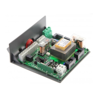
KER control unit
The KER electronic control unit can be used to control 1 motor with power not higher than
750W.
GENERAL WARNINGS
a) The wire connections and the operating logic should be in compliance with regulations in
force.
b) The cables featuring different voltage should be physically detached, or adequately insulated
by an additional shield of at least 1 mm.
c) The cables should be further fastened in proximity to the terminals.
d) Check all connections before powering the unit.
e) Check that settings of the Dip-Switches are the required ones.
f) Normally Closed inputs which are not in use should be short-circuited.
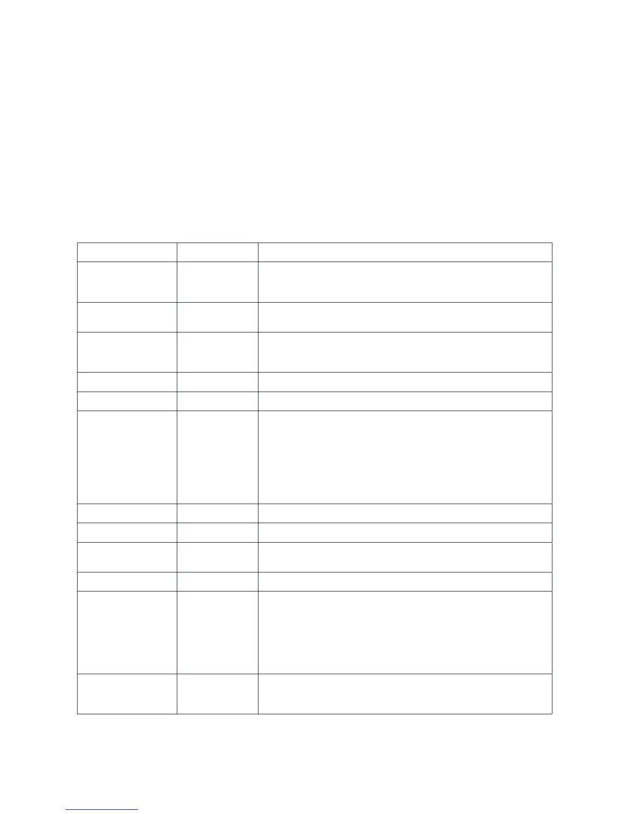
INPUT/OUTPUT FUNCTIONS
Terminals Function Description
L-N-GND Power supply Input, 23VAC, 50/60Hz (KER)
Input, 115VAC, 50/60Hz (KER 115V)
(1-Phase/2-Neutral/GND-earth)
MOT-COM-MOT Motor Connection to motor:
(MOT-move/COM-Common/MOT-move)
N-BLINK LAMP Output, flashing light connection
KER: 230VAC 40W max.
KER 115V: 115VAC 40W max.
SWO SWO Input, OPEN limit switch (Normally Closed contact)
SWC SWC Input, CLOSE limit switch (Normally Closed contact)
PHOT(CHIUDE) PHOT Input, connection of safety devices, N.C. contact (e.g. photocells):
- in the closing phase, when the contact is opened the motor is
stopped and its direction is immediately reversed;
- in the opening phase, the triggering of the contact has no effect
on the motor.
In the “Service man” operating mode, this contact acts as CLOSE
control signal. In this case connect it to a N.O. (Normally Open)
button.
STOP STOP Input, STOP push-button (Normally Closed contact)
COM COM Common, for all control inputs.
P.P (OPEN). Step-by-Step Input, Step-by-Step push-button (Normally Open contact)
In the “Service man” operating mode, it acts as OPEN control.
24 VAC 24VAC Output, power supply of accessories, 24VAC/200mA max
SCA-SCA Ch.II/Lock Non-insulated, free contact.
Configurable output through DIP-SWITCH 5.
DIP5 ON: Output, second radio channel of the incorporated
receiver (24VAC/3W max).
DIP5 OFF: Connection to the Lock optional card for the control of
the electric lock.
Do not connect the electric lock directly to the output.
SHIELD-ANT Antenna Connection of the extractable radio receiver card and the built-in
radio module
(SHIELD- DISPLAY/ANT-signal).
Note:
The control unit is equipped with a “P2” button with the same functions as the Step-by-Step
button, useful to control the automatic system during installation.