11
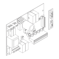
THINK Control Unit
The THIKS control unit can be used to control 1 single-phase, 230Vac motor or 1 three-phase, 400Vac motor with power not
exceeding 800W for single-phase motors and 2200W for three-phase motors.
GENERAL WARNINGS
a) The wire connections and the operating logic should be in compliance with regulations in force.
b) The cables featuring different voltage should be kept detached, or adequately insulated by an additional insulation of at least
1mm.
c) The cables should be further fastened in proximity to the terminals.
d) Check all connections before powering the unit.
e) Normally Closed inputs which are not in use should be short-circuited.
f) The Power supply mains should be connected to an omnipolar switch with contact opening distance of 3mm, or higher distance.
Check that upstream the electric system is provided with an adequate differential switch and an overcurrent switch.
INPUT/OUTPUT FUNCTIONS
THINK Control Unit
Terminal No. Function Description
1-2-3 Motor
Connection, 230Vac motor - single-phase:
1-Movement+capacitor/2-Common/3-Movement+capacitor
Connection, 400Vac motor - three-phase:
1-U/2-V/3-W
Check that the voltage selection jumper on terminals 36-37-38 is correctly positioned.
4-5 Flashing light
Connection of ashing light, 230Vac 40W max.
Connect a negative electric brake to this output.
5-6 AUX WARNING: Output, 230Vac 0,5A max.
7-8
Auxiliary capaci-
tor
Free N.O. (Normally Open) contact (10A max) for pickup auxiliary capacitor.
See wire diagram. At each start-up the contact is closed for 1.5 sec.
9-10 Courtesy light
Free N.O. contact (2A 150W) to control the Courtesy light which is timed according to the
TLS parameter.
11-12 24Vac Output, accessory power supply 24Vac/0,5A max
13-14 SCA/PhotoTest
Output, 24Vac/0,5A max. This can be preset as open gate indicator light or as checked de-
vices power supply (PhotoTest) through the TSTP logic.
In the event of presetting as PhotoTest, please refer to the diagram “Connection of checked
safety devices”
15 COM Common for limit switches and photocells
16 SWO Input, OPEN limit switch (N.C. contact)
17 SWC Input, CLOSE limit switch (N.C. contact)
18 PHOT 1 Input, Photocell 1 (N.C. contact). It can be disabled in the opening phase, see PHO1 logic.
19 PHOT 2 Input, Photocell 2 (N.C. contact). It can be disabled in the opening phase, see PHO2 logic.
20 PHOT 3 Input, Photocell 3 (N.C. contact). It can be disabled in the opening phase, see PHO3 logic.
21 PHOT 4 Input, Photocell 4 (N.C. contact). It can be disabled in the opening phase, see PHO4 logic.
22 STOP Input, STOP push-button (N.C. contact)
23 OPEN Input, OPEN push-button (N.O. contact).
24 CLOSE Input, CLOSE push-button (N.O. contact)
25 PED Input, pedestrian push-button (N.O. contact)
26 Step-by-step Input, step-by-step (N.O. contact)
27 COM Common for all other control inputs.
28-29 DAS
Input, safety edge contact.
Resistive edge: closed “ DAS” jumper.
Mechanical edge: open “DAS” jumper.
When the safety edge is activated, the gate movement stops. The gate movement is re-
versed for approximately 3 sec if the INVA logic is ON. If no safety edge is used: “DAS”
Jumper open, jumper between terminals 28-29.
30-31 Aerial
Connection of the antenna to the receiver extractable board (30-signal/31-screen).
32-33 2
nd
radio channel Output, 2
nd
radio channel of the two-channel extractable receiver.
 Loading...