19
4) TRANSMITTERS REMOTE LEARNING
If an already memorised transmitter is available in the receiver it is possible to carry out remote radio learning (without needing to access the control unit).
IMPORTANT: The procedure must be carried out with leaves in opening during TCA pause or with an open gate if the TCA logic is OFF. The
REM logic must be ON.
Proceed as follows:
1 Press the hidden key of the transmitter which is already memorised.
2 Press, within 5s, the key of the corresponding transmitter which is already memorised to associate to the new transmitter. The flashing light will turn on.
The flashing light switches on.
3 Press within 10s the hidden key of the new transmitter.
4 Press, within 5s, the key of the new transmitter to associate to the channel chosen at point 2. The flashing light will turn off.
5 The receiver memorised the new transmitter and immediately exits from programming.
5) DIAGNOSTICS
Each input is matched to one segment of the display; in the event of activation, it switches on according to the following diagram.
PHOT1
SWC
STOP
SWO
PHOT3
PHOT4
PHOT2
DAS
P.P. PED OPEN CLOSE
The Normally Closed (N.C.) inputs are represented by vertical segments. The Normally Open (N.O.) inputs are represented by horizontal segments.
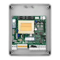
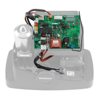
DL1: If the card is turned on and running the LED lights up.
DL2: If the control unit communicates with an Encoder the LED lights up.
DL3: If the control unit communicates with an Encoder the LED lights up.
6) ERROR MESSAGES
The control unit checks the correct operation of the safety devices.
In the event of faults the following messages can be displayed:
ERR1 Error, check photocells. Check connections and the correct operation of photocells.
ERR2 Activation of the anti-crash amperometric sensor. Check the presence of any obstacles.
ERR3 Encoder Error. Check the connections and the correct operation of the Encoder.
ERR4 Triggering of the motor protection switch.
ERR5 Error, photocells
7) FUSES
F1 Protection fuse, accessories
F2 Protection fuse, logic board
F3 Protection fuse, flashing light and electric brake.s
F4 Primary protection fuse of the transformer.