07/ 2018
BENNING ST 725
26
Resistance to external voltages: max. 276 V
For non-sinusoidal current supply, an additional error has to be considered:
crest factor of > 1.4 to 2.0, additional error + 3.1 %
7.6 Cord test
- measurement of the protective conductor resistance according to 7.1
- measurement of the insulating resistance according to 7.2
- line break testing of the external conductor (L) and the neutral conductor (N)
- short-circuit testing of the external conductor (L) and the neutral conductor (N)
7.7 Tripping time measurement of RCDs
Measuring range Resolution Measuring accuracy
10 ms - 500 ms 1 ms 5 % ± 2 digits
Testing current / polarity:
30 mA sinussoidal/0° and 180°
150 mA sinussoidal /0° and 180°
Preset limiting value: 200 ms (30 mA), 40 ms (150 mA)
7.8 Protective conductor current (direct measurement method) (optional measuring
adapters 044140 or 044141)
Measuring range Resolution Measuring accuracy
0.25 mA - 9.99 mA 0.01 mA 5 % ± 2 digits
Nominal voltage:
3 x 400 V ± 10 % (as mains feed-in)
Rated current:
16 A or 32 A
Preset limiting value:
3.5 mA
7.9 Voltage measuring on external shock-proof socket
Measuring range Resolution Measuring accuracy Overload protection
50 V - 270 V
AC
1 V 5 % ± 2 digits 300 V
Display:
- voltage between the external conductor (L) and the neutral conductor (N)
- voltage between the external conductor (L) and the ground conductor (PE)
- voltage between the neutral conductor (N) and the ground conductor (PE)
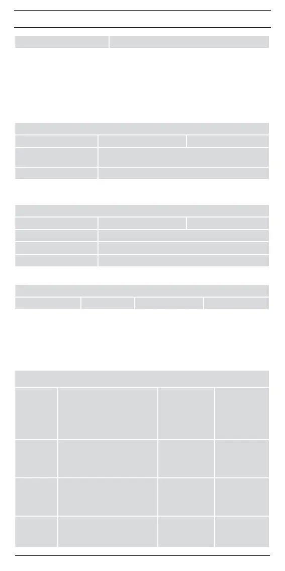
7.10 Limiting values according to DIN VDE 0701-0702 and ÖVE/ ÖNORM E 8701-1
Note:
Limiting values preset in bold are stored in the BENNING ST 725.
Protection class I
Protection class
II, III
Line test
Protective
conductor
resistance
R
PE
Forcordswithratedcurrent≤16A:
≤ 0.3 Ω
up to a length of 5 m, per
further7.5m:additional0.1Ω,
max.1Ω,
For cords with higher rated cur-
rents the calculated ohmic resistance
value applies.
≤ 0,3 Ω
(see protection
class I)
Insulating
resistance
R
ISO
≥ 1 MΩ
≥2MΩforprovingsafedisconnec-
tion (transformer)
≥0.3MΩfordeviceswithheating
element
≥ 2 MΩ
(protection class II),
≥0.25MΩ
(protection class III)
≥ 1 MΩ
Protective
conductor
current
I
EA
/ I
LEAK
≤ 3.5 mA
on conductive parts with PE con-
nection
1 mA/ kW for devices with heating
elements P > 3.5 kW
Contact
current
I
EA
/ I
LEAK
≤ 0.5 mA
on conductive parts without
PE connection
≤ 0.5 mA
on conductive parts
without
PE connection