07/ 2018
BENNING ST 725
33
9.3 Cord test
The cord test can be used both for the testing of IEC power cords (device connecting cables
with IEC coupler) and for the testing of cable reels, multiple distributors and extension cables.
9.3.1 Testing of IEC power cords (IEC adapter cables)
- Disconnect the plug of the mains connection cable from the socket K of the BENNING ST 725.
- Connect the IEC power cord to be tested to the BENNING ST 725 by means of the IEC
connector J.
- Press the -key
2
to start the automatic testing procedure.
- The test starts with measuring the protective conductor resistance R
PE
.
- Depending on whether the value is higher or lower than the limiting value, a or a is
indicated next to the R
PE
-symbol.
The protective conductor resistance depends on the length and cross-section
of the line to be tested.
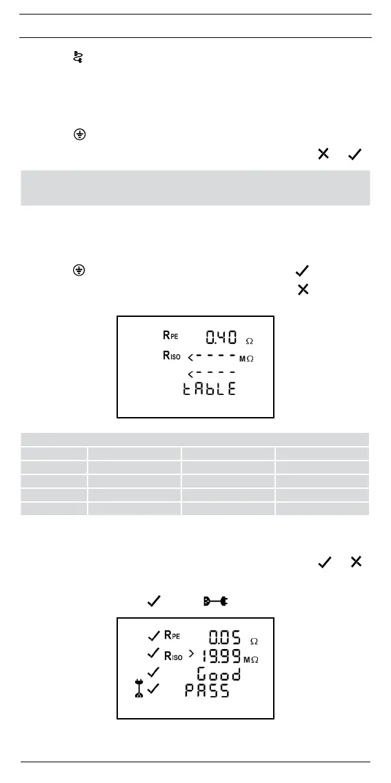
- If R
PE
ishigherthantheadmissiblelimitingvalue(≤0.3Ωuptoalengthof5m)butlower
than 1 Ω, the measured value will bedisplayedwithouta rating, the “tAble” symbol will
appear on the display and the test procedure will be stopped. The responsible testing staff
determines by means of the limiting value table (see section 7.10 or the table on the rear
of the BENNING ST 725) and by means of the line length of the test object whether the
displayed measured value is acceptable or not.
Press the -key
2
to give the measured value a positive rating and a will be displayed
next to the R
PE
symbol. The test procedure will be continued.
Press the
-key
3
to give the measured value a negative rating and a
will be displayed
next to the R
PE
symbol. "FAIL" appears on the display to confirm that the measurement has
been stopped.
- Please refer to Table 1 for typical resistance values of lines.
Cross-section
Length 1.0 mm² 1.5 mm² 2.5 mm²
5 m 0.1Ω 0.06Ω 0.04Ω
10 m 0.2Ω 0.12Ω 0.08Ω
25 m 0.5Ω 0.3Ω 0.2Ω
50 m 1.0Ω 0.6Ω 0.4Ω
Table 1:
Resistance values of the protective conductor depending on length and cross-section
- After the R
PE
test has been passed, the measurement of the insulating resistance is carried
out automatically.
- Depending on whether the value is higher or lower than the limiting value, a or a is
indicated next to the R
ISO
symbol.
- After the R
ISO
test has been passed, the external conductor (L) and the neutral conductor
(N) are checked for line breaks and short-circuits. A passed test regarding line breaks and
short-circuits is indicated by a next to the and the "Good“ symbol.
- The "PASS" symbol confirms successful testing of the entire testing procedure.
- If the test regarding line breaks, short-circuits or inversion (L/N) has failed, one of the
following symbols will be displayed instead of the “Good" symbol:
- "OPEN" symbol: