Q7C3 LCD Monitor Service Guide
Engineering Specification
14
3.7 Panel optical Characteristics
Item Unit Conditions Min. Typ. Max.
Horizontal (Right)
CR = 10 (Left)
60
60
70
70
-
Vertical (Up)
CR = 10 (Down)
60
60
70
70
-
Horizontal (Right)
CR = 5 (Left)
70
70
80
80
-
-
Viewing Angle [degree]
Vertical (Up)
CR = 5 (Down)
70
70
80
80
-
-
Contrast ratio
Normal Direction 250 450 -
Raising Time - 4 5
Falling Time - 12 20
Response Time (Note 1)
[msec]
Raising + Falling - 16 25
Red x 0.61 0.64 0.67
Red y 0.31 0.34 0.37
Green x 0.26 0.29 0.32
Green y 0.58 0.61 0.64
Blue x 0.11 0.14 0.17
Color / Chromaticity
Coordinates (CIE)
Blue y 0.04 0.07 0.10
White x 0.28 0.31 0.34
Color Coordinates (CIE) White
White y 0.30 0.33 0.36
White Luminance @ CCFL 7.0mA
(center)
[cd/m
2
]
200 260 -
Luminance Uniformity (Note 2) [%] 75 80 -
Crosstalk (in 75Hz) (Note 3) [%] 1.5
Note:
1. Viewing Angle, Contrast Ratio, Response Time, Reflectance, and Chromaticity are measured at panel center.
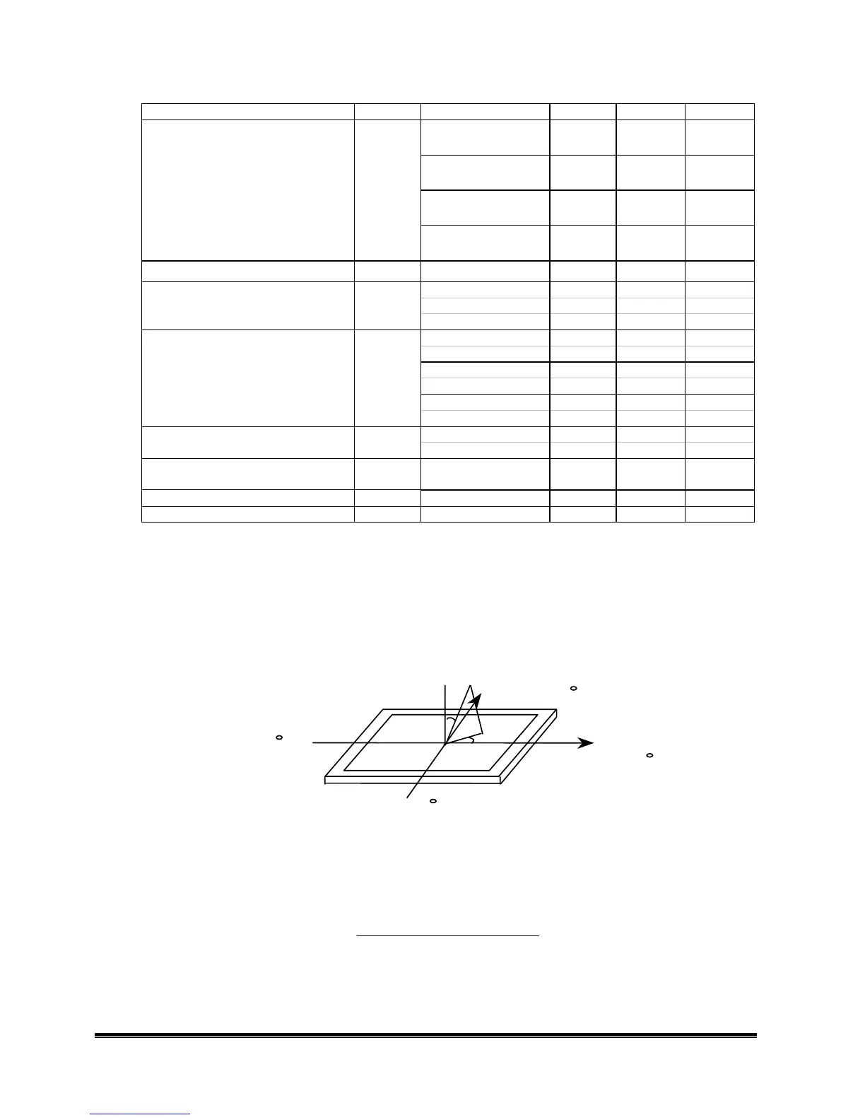
2. Viewing Angle(θ, ψ)
See figure below
Measurement is done on position 1.
Viewing angle origine is the axis normal to the flat panel. Left (L) and Right (R) valu
are the maximum angles for which CR=10. Up (U) and (D) value are the maximum
angles for which CR=10.
Normal
E
y
È
Ö
x
Ö = 0 , Right
Ö = 90 , Up
Ö = 180 , Left
Ö = 270 , Down
3.Contrast Ratio (CR) is defined mathematically as:
)0φ ,0θ(at
(Min.) el Black Levin Luminance
(Max.) LevelWhite in Luminance
oo
==