Balanced Flue
Carefully remove the packing from
around
the boiler.
Fit the water flow
and
return fittings into the required positions
on
the boiler.
If
only one flow
and
one return connection is required, then they should preferably
be
positioned on opposite sides of the boiler.
Place
the
boiler
in
the
required installation position
and
remove
the
top
panel,
by
lifting
it
upward,
and
the
lower front panel
by
pulling it forward. Place the
top
and
front panels safely to
one
side so
that
they will not
be
damaged.
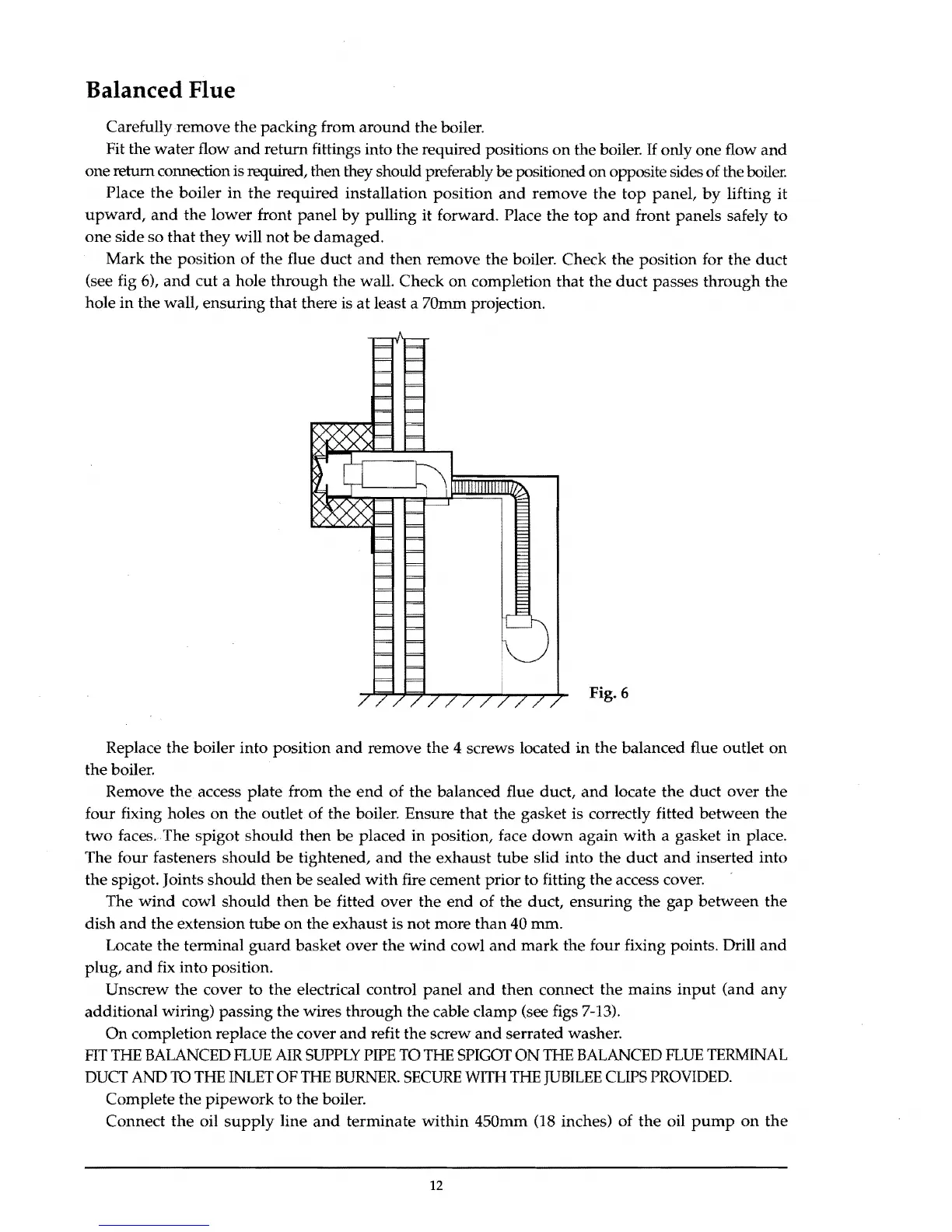
Mark the position of
the
flue duct
and
then remove
the
boiler. Check the position for
the
duct
(see fig 6),
and
cut a hole
through
the walL Check
on
completion that the
duct
passes through the
hole
in
the wall, ensuring
that
there is
at
least a 70mm projection.
Fig. 6
Replace the boiler into position
and
remove
the
4 screws located
in
the balanced flue outlet
on
the boiler.
Remove
the
access plate from
the
end
of the balanced flue duct,
and
locate the duct over the
four fixing holes
on
the outlet
of
the boiler. Ensure
that
the gasket is correctly fitted between the
two
faces.
The
spigot should
then
be placed in position, face
down
again
with
a gasket in place.
The four fasteners should
be
tightened,
and
the exhaust tube slid into the duct
and
inserted into
the spigot. Joints should then
be
sealed
with
fire cement prior to fitting the access cover.
The
wind
cowl should
then
be
fitted over the
end
of the duct, ensuring the
gap
between
the
dish
and
the extension tube
on
the exhaust is not more
than
40 mm.
Locate
the
terminal
guard
basket over the
wind
cowl
and
mark
the four fixing points. Drill
and
plug, and fix into position.
Unscrew
the
cover to the electrical control panel
and
then connect the mains
input
(and
any
additional wiring) passing the wires through the cable clamp (see figs 7-13).
On
completion replace
the
cover
and
refit
the
screw
and
serrated washer.
FIT
THE
BALANCED
FLUE
AIR
SUPPLY
PIPE
TO
THE
SPIGOT
ON
THE
BALANCED
FLUE
TERMINAL
DUCT
AND ro
THE
INLET
OF
THE
BURNER.
SECURE
WITH
THE
JUBILEE
CLIPS
PROVIDED.
Complete the pipework to the boiler.
Connect
the
oil
supply
line
and
terminate within 450mm (18 inches) of
the
oil
pump
on
the
12