Long period switching off
In case of absence for long periods of time, set the mode selector
(1-g.1a)to (OFF).
Then,closethegastappresentonthesystem.Inthiscase,anti-frost
deviceisdeactivated:emptythesystems,incaseofriskoffrost.
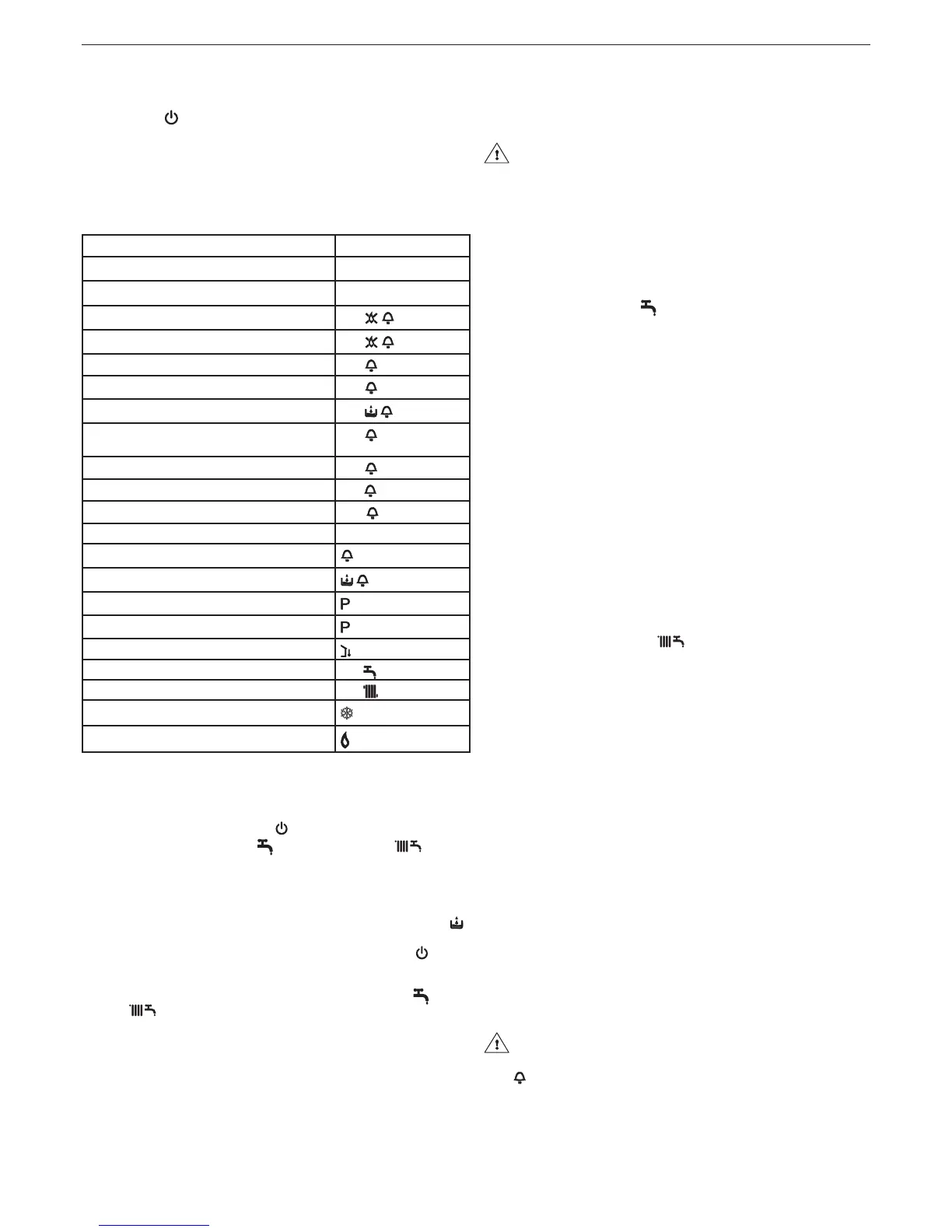
4.4 Light signals and faults
Theoperatingstatusoftheboilerisshownonthedigitaldisplay,
belowisalistofthetypesofdisplays.
4.5 Adjustments
Theboilerhasalreadybeenadjustedbythemanufacturer.
Ifitisnecessarytoadjustitagain,forexampleafterextraordinary
maintenance, after replacement of gas valve or after gas conversion,
carryoutthefollowingprocedure.
The maximum output adjustment must be carried out in
the sequence indicated exclusively by qualied personnel.
- removetheshellunscrewingthexingscrewsA(g.6)
- unscrewbytwoturnsthescrewofthepressuretestpointdown-
stream the gas valve and connecting the pressure gauge
- disconnect the compensation inlet of the air distribution box
4.5.1 Ciao S C.S.I.: Maximum power and minimum domestic
hot water adjustment
- Fullyopenthe hot water tap
- on the control panel:
- set the mode selector to (summer)(g.2a)
- turn the domestic hot water temperature selector to its maximum
(g.8a)
- powertheboilersettingthesystemmainswitchto“on”
- check that the pressure on the pressure gauge is stable; or with
a milliammeter in series to the modulator, make sure that the
modulatorsuppliesthemaximumavailablecurrent(120mAfor
G20and165mAforLPG).
- carefullypriseouttheprotectioncapoftheadjustmentscrews,
usingascrewdriver(g.15)
- with a fork spanner CH10 use the adjustment nut of the maximum
output in order to obtain the value indicated in table "Technical data"
- disconnect the modulator faston
- wait until the pressure on the pressure gauge is stable at minimum value
- paying attention not to press the internal shaft, use anAllen
spanner to turn the red adjustment screw for domestic hot water
minimum temperature regulation, calibrating it until the pressure
gauge reads the value indicated in the table "Technical data"
- reconnect the modulator faston
- close the domestic hot water tap
- carefullyrettheprotection cap of the adjustment screws.
Ciao S R.S.I.: Maximum and minimum power adjustment
- Set the function selector to (winter)(g.2b)
- Remove the housing and access the card
- Insert the jumpers JP1 and JP2
- Bring the trimmer P2 to the maximum value, using a screwdriver
(turnclockwise)
-Powertheboilersettingthesystemmainswitchto“on”
- Check the pressure on the pressure gauge is stable; or, with a
milliammeter in series to the modulator, make sure the modulator
suppliesthemaximumavailablecurrent(120mAforG20and165
mAforLPG)
-Useascrewdrivertocarefullypriseouttheprotectioncapofthe
adjustment screws
- With a fork spanner CH10, use the adjustment nut of the maximum
output in order to obtain the value indicated in the table "Technical
data"
- Disconnect the modulator faston
- Wait until the pressure on the pressure gauge is stable at minimum
value
- Use an Allen spanner to set the red adjustment screw at the
minimum output, calibrating it until the pressure gauge shows the
value indicated in the table "Technical data"
- Reconnect the modulator faston
-Disconnecttheboilerfromthepowersupply
- Remove the jumpers JP1 and JP2
-Carefullyrettheprotectioncapoftheadjustmentscrews.
4.5.2 Minimum and maximum heating electric adjustment
The “electric adjustment”functionisactivatedanddeactivated
exclusivelybythejumper(JP1)(g.16).
ADJ appearsonthedisplaytoindicatethatthecalibrationpro-
cedureisunderway.
Thefunctioncanbeenabledinthefollowingway:
- bypoweringthecardwiththejumperJP1insertedandthemode
selectorinwinterposition,independentlyfromthepossiblepres-
ence of other operation request.
- byinsertingthejumperJP1,withthemodeselectorinwinterposi-
tion, without heat request in progress.
BOILER STATUS DISPLAY
Stand-by -
OFF status OFF
ACF module lockout alarm
A01
ACF electrical fault alarm
A01
Limit thermostat alarm
A02
Air pressure switch alarm
A03
H2O pressure switch alarm
A04
NTCdomesticwaterfault(C.S.I.andR.S.Ionly
withexternalstorageheaterwithprobe)
A06
NTC heating fault
A07
Parasiteame
A11
Electric calibration min and max heating
ADJ
Transient awaiting ignition 88
°C
ashing
Air pressure switch intervention
ashing
H2O pressure switch intervention
ashing
PreheatingFunctionactive(onlyC.S.I.)
Preheatingheatrequest(onlyC.S.I.)
ashing
External probe present
Domestic water heat request 60
°C
Heating heat request 80
°C
Anti-freeze heat request
Flame present
To restore operation (deactivate alarms):
Faults A 01-02-03
Position the function selector to (OFF),wait5-6secondsthen
set it to the required position (summermode)or (winter
mode).
If the reset attempts do not reactivate the boiler, contact the Techni-
cal Assistance Centre.
Fault A 04
Inadditiontothefaultcode,thedigitaldisplayshowsthesymbol .
Checkthepressurevalueindicatedbythewatergauge:
if it is less than 0.3 bar, position the function selector to (OFF)
andadjustthellingtap(Lg.13forC.S.I.-externalforR.S.I.)until
the pressure reaches a value between 1 and 1.5 bar.
Then position the mode selector to the desired position (sum-
mer)or (winter).
The boiler will perform one purge cycle lasting approximately 2
minutes.
If pressure drops are frequent, request the intervention of the Tech-
nical Assistance Service.
Fault A 06 (only C.S.I.)
Theboileroperatesnormally butcannotreliably maintainacon-
stant domestic hot water temperature, which remains set at around
50°C. Contact the Technical Assistance Centre.
Fault A 07
Contact the Technical Assistance Centre.
 Loading...


