Réglages :
Se munir d’un multimètre.
- Le réglage commence par le 0/4mA.
- Amener le servomoteur en position fer-
mée et le mettre hors tension.
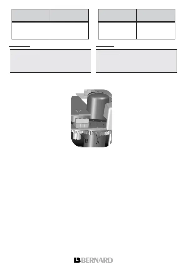
- Lire la résistance entre les
plots T1 et T2. Faire tourner le
grand pignon (A) jusqu’à ce que
la valeur de résistance
dépasse 0 Ohm et augmente
régulièrement puis tourner en
sens inverse afin de revenir à
une valeur proche de 0 Ohm. Le
potentiomètre est ainsi calé en
début de piste.
- Brancher le multimètre en position
milliampèremètre en série sur la sortie du
TAM (voir schéma en dernière page).
- Alimenter le servomoteur.
- Régler précisément le 0/4 mA grâce au à
la vis de réglage marquée "0/4mA".
- Amener maintenant le servomoteur en
position ouverte.
- Tourner la vis de réglage repérée "20mA"
pour lire exactement 20mA.
- Revenir en position fermée et vérifier que
la valeur du 0% est bien répétable et
proche de 0/4 mA.
8. OPTION COMMANDE PROPORTIONNELLE
Cette carte permet de positionner la
vanne dans des positions intermédiaires.
Effectuer le raccordement électrique suiv-
ant le schéma "version positionneur".
Settings :
A multimeter is required for these settings.
- Start by adjusting the 0/4mA.
- Drive actuator to the closed position and
switch the power supply off,
- Read Ohm value between T1 &
T2 test points. Rotate the large
pinion (A) so that the reading
exceeds 0 Ohm and increases
regularly. Turn backwards to get
a value as close to 0 Ohm as
possible.
The potentiometer is now posi-
tioned at the beginning of its
track.
- Connect the multimeter to read a
mA value at the output of the TAM (see
schematic on last page).
- Turn the power supply on.
- Precisely adjust the 0/4 mA with the
adjustment screw marked as "0/4mA".
- Drive the actuator to the open position,
- Turn the screw marked "20mA" to read
exactly 20 mA on the milliampermeter.
- Come back to the closed position and
check that the output signal shows a close
to 0/4 mA and repeatable value.
8. PROPORTIONAL CONTROL OPTION
The proportional control board allows to
drive the valve to intermediate positions.
Perform the electrical wiring according to
the “Positioner version” diagram.
Attention : certaines parties de la
carte sont sous haute tension, ne
pas faire un réglage du 0% avec le
servomoteur sous tension.
12
24
30
150
750
1050
Alimentation
Volt
Charge maxi
admissible Ohm
12
24
30
150
750
1050
Power Supply
Volt
Maximum
Load Ohm
Warning : some parts of the electron-
ic board are supplied with high volt-
age. Never perform a 0% setting
when the actuator is power supplied.