28
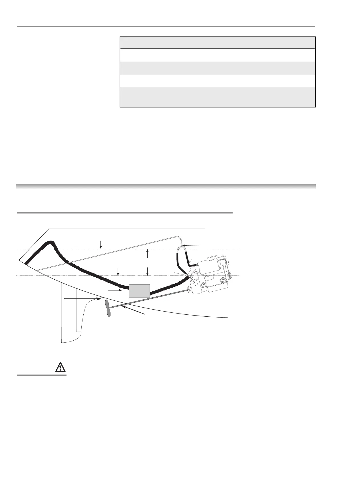
TYPICAL YACHT INSTALLATION
Anti syphon valve
or T piece fitted here
300mm
minimum
Waterlock
Silencer
X
a
Normal sea
water level
Maximum sea water level when heeled
(on the centre line of the boat)
Exhausts
Beta 10 BZ482 / Beta 16 BD722 / Beta 25
Standard 50mm 50mm 50mm
Option 1
5
/
8
” is available in SS 1
5
/
8
”1
5
/
8
”1
5
/
8
”
High rise water injection bend SS 50mm 50mm 50mm
Cross over injection bend SS
50mm 50mm 50mm
to suit Volvo replacement engines.
EXHAUSTS
Allow at least
10% of propeller
diameter for tip
clearance to hull
If a rope cutter is fitted, allow
approximately
1
/
2
” for movement of engine, see
manufacturer’s literature
WARNING:
(1) One of the most common
problems with engine installation is
water entering the exhaust manifold
from the exhaust system by
syphoning. This can occur when the
point of water injection (X) on the
engine is close to or below the water
line. Water entering the pistons can
cause bent con rods, emulsified
engine oil and a wrecked fuel pump!
Its best avoided!
(2) The diagram shows a typical
installation. It is essential that the
small black rubber hose connecting
the heat exchanger with the injection
bend is removed and replaced by a
hose marked ‘a’. This must be of
sufficient length to
supply either a T piece or an anti
syphon valve sited at least 300mm
(12 inches) above the water line and
on the centre line of the boat. The
pipe then returns to the injection bend
and the sea water is pumped down
the exhaust pipe.
(3) The exhaust back pressure should
not exceed 3.1 inches of Hg.
(a) A correctly installed engine as
described in this handbook will meet
the exhaust emission requirements of
Directive 2003/44/EC amending the
Recreational Craft Directive 94/25/EC.
(b) For compliance with exhaust
emissions requirements, engines must
have correctly installed exhaust
systems. To ensure exhaust emissions
are kept within permissible limits it is
most important to reduce exhaust
back pressure to a minimum, whilst
ensuring exhaust is adequately
muffled. Back pressure increases as
exhaust length increases and from
bends in the exhaust system. The
exhaust back pressure, measured with
the exhaust system connected and the
engine running at full speed, must not
exceed 80mmHg (3.1 inches Hg / 42
inches WG). The correct measuring
point is at the
position where the exhaust connects
to the exhaust manifold. That is before
the water injection elbow or dry
exhaust bellows.
Wet Exhaust hose should be matched
to the injection bend sizes detailed
above.
 Loading...