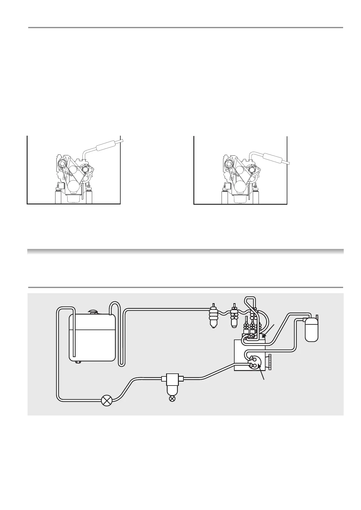
FUEL SUPPLY & LEAK OFF -
A typical system is shown below
(1) Fuel tank
(2) Injection pump
(3) Injection nozzle
(4) Injection pipe
(5) Mechanical fuel feed
pump with priming lever
(6) Fuel filter
(7) Fuel water separator
(8) Overflow/leak off
(9)
Drain plug
(10) Air vent
(11) Stop cock
(12)
F
uel pipe loop
29
Ensure exhaust raises then falls to outlet
The exhaust system installed in a
canal boat or work boat with a dry
exhaust should be
1
1
/
2
” minimum ID.
The engine is fitted with a 1
1
/
2
” BSP male
connector when a dry exhaust system is
specified. A flexible exhaust bellows and
dr
y exhaust silencer should be used. It is
up to the installer to work out his own
pipe run but care should be taken as
follows:
(1) Ensure that rain water cannot
enter the exhaust port and run
back down the system, flooding
the silencer and eventually the
engine.
(2)
The system should be lagged if
there is any danger of the crew
getting near it.
(3) A dry exhaust system will give off
considerable heat and suitable
ventilation must be provided.
(4) The exhaust back pressure should
not exceed 3.1 inches of Hg.
DRY EXHAUST SYSTEM
37



 To Next Page