DF MANUAL INSTALLATION
Manual version 3.0 - North America (15-07-2014) en-15
en
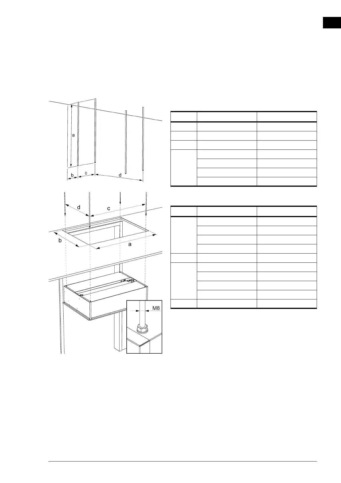
2.4.2 Suspending and securing the unit
1. Position the four M8 (metric) screw threads. Make sure
the thread rods are perpendicular.
Dimensions for free-hanging and recessed units.
Dimensions of hole and suspension for cassette model
SIZE TYPE DIMENSIONS
a all DF F, R as needed
b all DF F, R 35 mm(1 3/8")
c all DF F, R 290 mm(11 13/32")
d DF 100-F, 100-R 896 mm(35 9/32")
DF 150-F, 100-R 1396 mm(54 31/32")
DF 200-F, 200-R 1896 mm(74 21/32")
DF 250-F, 250-R 2396 mm(94 11/32")
SIZE TYPE DIMENSIONS
a DF 100-C 1012 mm(39 27/32")
DF 150-C 1512 mm(59 17/32")
DF 200-C 2012 mm(79 7/32")
DF 250-C 2512 mm(98 29/32")
b all DF C 705 mm(27 3/4")
c DF 100-C 937 mm(36 7/8")
DF 150-C 1437 mm(56 9/16")
DF 200-C 1937 mm(76 1/4")
DF 250-C 2437 mm(95 15/16")
d all DF C 641 mm(25 1/4")