DF MANUAL INSTALLATION
Manual version 3.0 - North America (15-07-2014) en-21
en
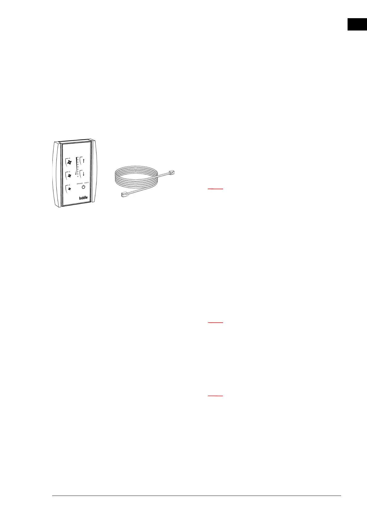
2.7 Installing the control panel and external controls
2.7.1 Control panel details
Positioning
• You may fix the control panel either to the wall or to a
standard junction box.
Cabling
n Take the following into account, otherwise faults may
occur:
- The control cable between the control panel and the
(first) connected unit may not be longer than 30 m
(98 ft).
- Keep control cables away from electromagnetic fields
and interference sources such as high-voltage cables
and fluorescent-light starters.
- Lay control cables out straight or roll them bifilarly
by folding cables in half before rolling them. This sig-
nificantly reduces inductance.
- Do not remove the dummy plug, unless otherwise
stated.
n Use Biddle control cables only (Type RJ4). Standard
modular telephone cable is NOT suitable.
Multiple units operated from one single control panel
• A maximum of 8 units can be connected to a single con-
trol panel.
n The RSR receiver module counts as one unit.
• Units are daisy chained using Biddle control cables and
Connectors
E and G.
• The total length of the control cables must not exceed 30
m (98 ft). If the distance is too great, an additional control
panel must be connected.
• Configure any one unit as a master. The sequence of the
connected units is not important.