INSTALLATION COMFORT AIR CURTAIN
en-26
en
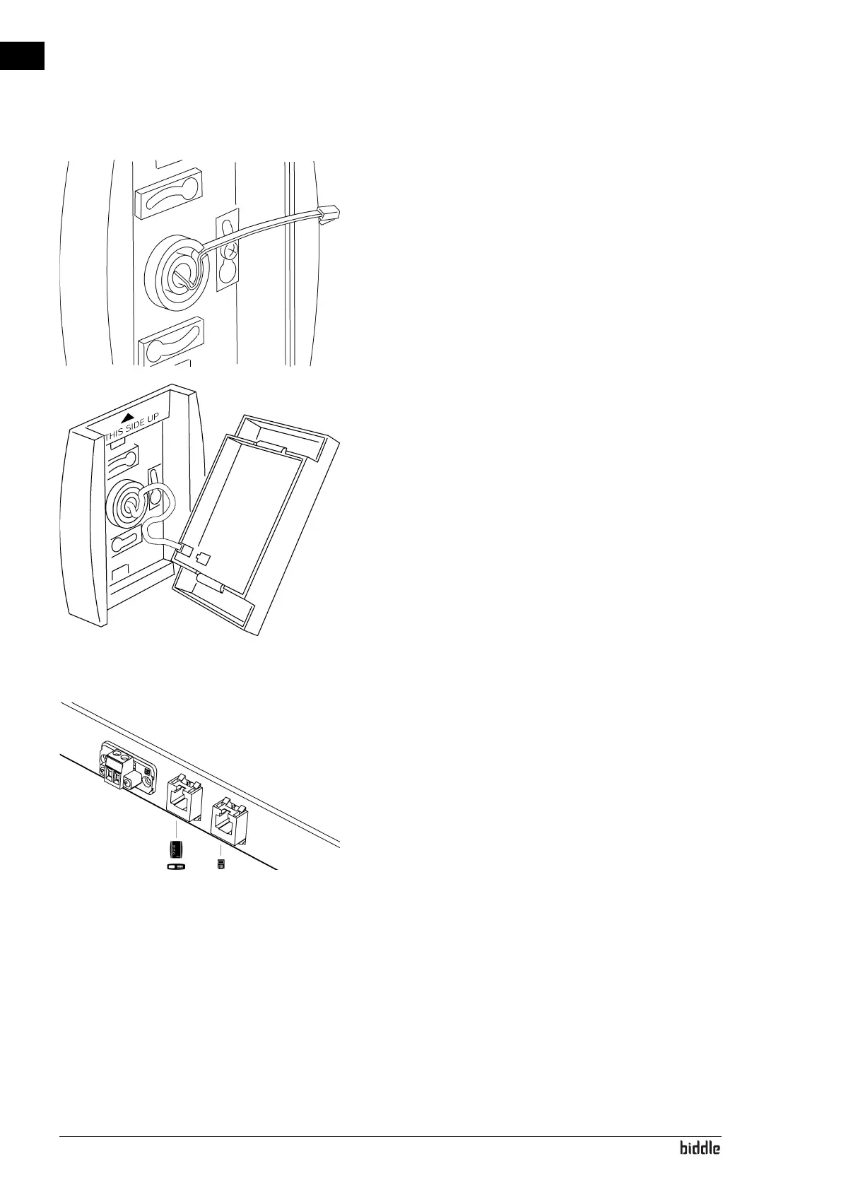
4. Secure the cable in a tension-free state.
The cable should protrude by approx. 9 cm(3 1/2").
5. Optional:
Set the dip switches on the front plate.
6. Attach the control cable’s connector to the PCB.
7. Replace the front plate onto the rear plate.
See also:
2.7.2 "Control panel settings" on page 22
6.5 "Biddle control cable composition" on page 43
2.7.7 Connecting control panel to unit
The control panel is connected to one of the two modular
unit connectors (marked with Symbols
E and H).
The two sockets are identical.