REV B 3-4 605228
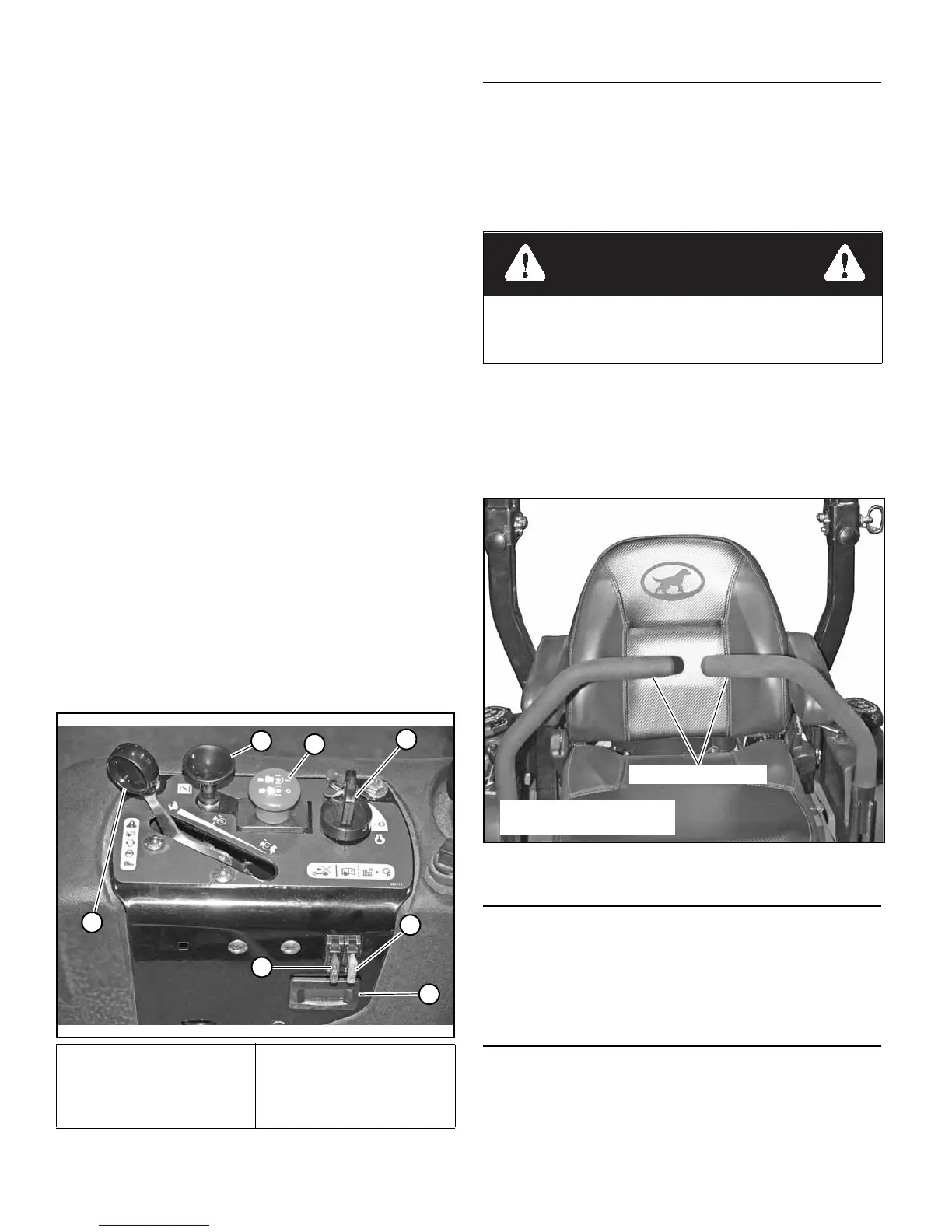
Control Panel
IMPORTANT: When access is required under the seat
platform and the seat is equipped with the optional arm
rests, make certain to place the control arms in the park
brake position and pivot the arm rests upward before plac-
ing the seat platform in the full forward position to prevent
arm rest damage.
A. Throttle control (Figure 3-1) — a cable is linked to
engine throttle for controlling engine speed. Move lever
forward to increase engine rpm, move lever rearward to
decrease engine rpm.
B. Choke control (Figure 3-1) — (Units with a separate
throttle and choke controls) a cable is linked to manually
operate the engine choke. When the control knob is in the
down position, the choke is in the off (run) position.
When the control knob is pulled up, the choke is in the on
(start) position. Do not operate the machine in the on
(start) position.
C. Deck clutch switch (Figure 3-1) — this switch engages
the deck. Pull the switch up to engage and push switch
down to disengage the clutch.
IMPORTANT: For additional clutch information refer
to the Mower deck operation section of this manual.
D. Ignition switch (Figure 3-1) — a three position switch:
off, run, and start. With key inserted, rotate it clockwise
to START position; release key when engine starts, and
switch will automatically return to the RUN position.
E. Electronic hour meter (Figure 3-1) — registers 1/10
hour increments up to 9,999.9 total hours. Connected to
the ignition switch, the meter records the accumulative
time while the ignition key is switch to the RUN position.
F. 10 amp fuse (Figure 3-1) — Main - 10 amp, blade-type.
G. 15 amp fuse (Figure 3-1) — Clutch/Aux - 15 amp,
blade-type
Controls
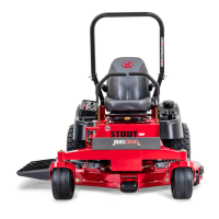
A. Steering control levers (Figure 3-2 & Figure 3-3) —
these levers control the mower’s speed, direction,
stopping, and park brake. These levers are used to steer,
accelerate, decelerate and change direction. When the
steering control levers are in the park brake position the
mower will not move when the engine is on and the drive
pumps are operating.
B. Deck lift pedal (Figure 3-4) — the deck lift pedal is used
to raise or lower the deck. Push on the pedal to raise the
deck and then place the deck height locking pin into the
desired cutting height hole.
Push the deck lift pedal to raise the deck when going over
obstructions.
Lights
The BigDog
®
Stout mower comes equipped with operating
lights mounted in the front mower frame. There is no dedicated
“ON/OFF” switch for these lights. These lights come on when
the ignition switch is in the “RUN” position and go off when the
ignition switch is in the “OFF” position. Figure 3-5
Safety Start Interlock System
The mower is equipped with a safety start interlock system
consisting of the park brake switches, seat switch, and deck
clutch switch.
Check the mower’s safety start interlock system daily,
prior to operation. This system is an important mower safety
feature. It should be repaired immediately if it malfunctions.
A. Throttle
B. Choke
C. Deck clutch switch
D. Ignition switch
E. Hour meter
F. 10 amp fuse
G. 15 amp fuse
Figure 3-1
The parking brake may not hold the mower if parked on a
slope. Block or chock the machine when parked on a
slope.
Figure 3-2
Shown with steering control
levers in neutral position
Steering control lever