2.7 PROBE PORT WIRING
The probe port has been provided to allow users to interface bed probes directly to the
motherboard without the need for a BAT85 diode to act as a protection against high
voltages. The probe signal pin connects to an internal optocoupler that in turn triggers the
pin connected to the microcontroller.
Depending on the type of probe you are using, you may need to add a jumper to activate
the internal 12k pull up resistor between the probe positive voltage rail and the probe signal
pin. This will be the case if you are using an “NPN” style probe where the output pulls to
ground when it is active. You can tell this by checking the output of your probe using a
multimeter. If it floats when it is not active (with nothing else connected to it) and then goes
to ground when it is active, it is an NPN style probe. If it goes to the positive rail when active
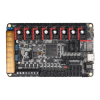
then it is a PNP style probe. The image below shows where the jumper to activate the 12k
pull up resistor is located.
Regardless of the kind of probe you are using, you will need to enable the internal pull-
down resistor on the probe input pin in order for it to generate an output signal. Please refer
to the pin configuration instructions for the specific firmware that you are using to find out
how to enable a pull down resistor on the probe input pin (PC5).

 Loading...