3 STEPPER DRIVER OPERATIONAL MODES
3.1 STEP/DIR MODE
If you are using drivers that do not support configuration over a serial port then you will
need to operate them in step/dir mode and set the jumpers beneath the stepper driver
according to the microstepping you desire.
Each driver will have its own microstepping table so we do not attempt to speak on behalf
of the driver manufacturer in our manual. Please consult the datasheet of your driver to
determine what signals need to be applied to the microstepping configuration pins in order
to achieve the microstepping you desire.
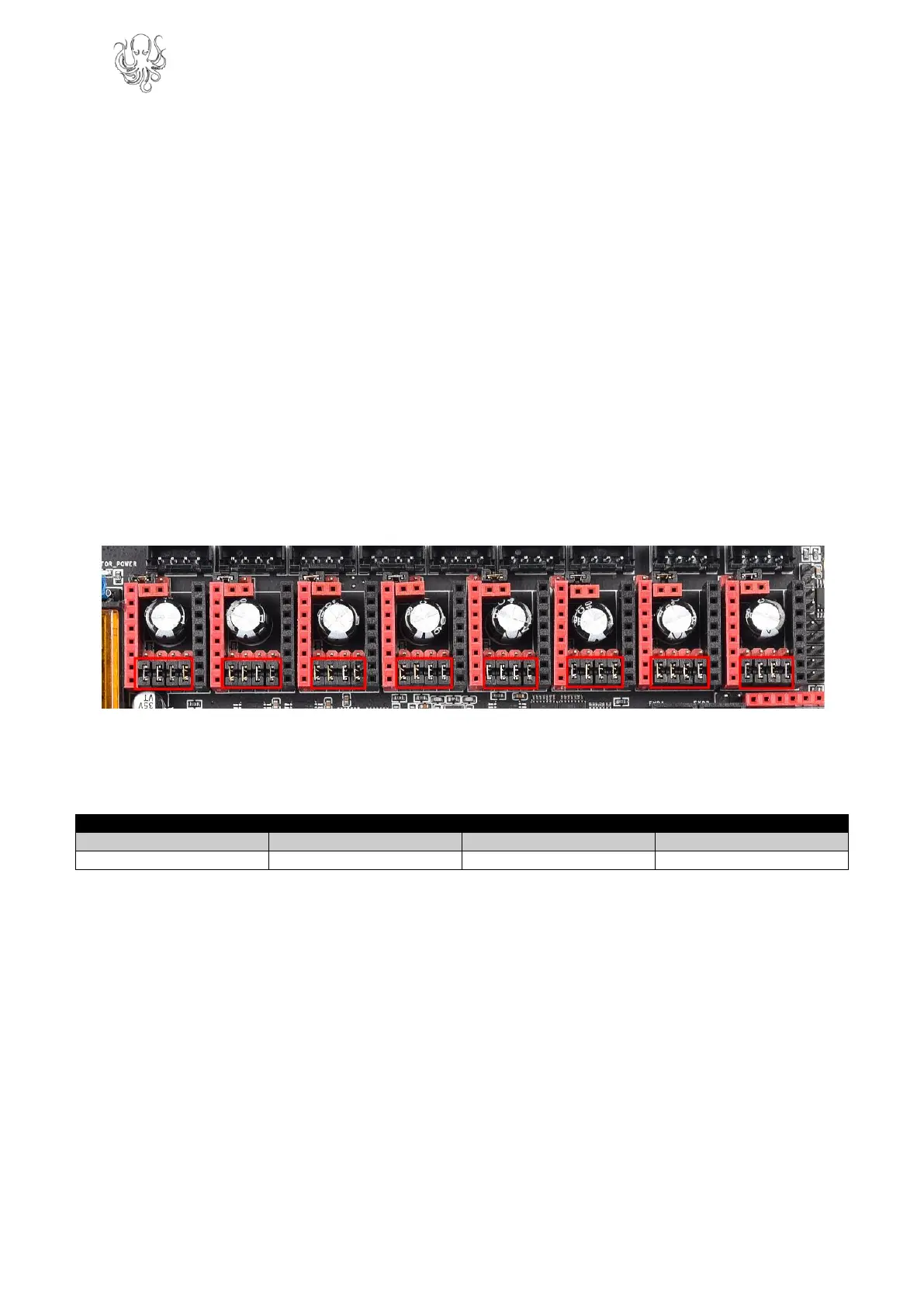
Nevertheless, below you will see a figure which will help you to identify which jumpers
correspond to the pins that your drivers will use to configure microstepping and we have
additionally included a section in appendix A1 which contains the microstepping tables for
some of the most common drivers. This should be viewed as a convenience to the user and
we still recommend that you consult the datasheet of your driver manufacturer.
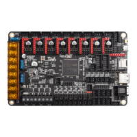
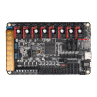
In the above image the red rectangle isolates the groups of driver pins. For the purpose of
running the drivers in step/dir mode the pinout can be described as per the table below
(note that this is not the actual pinout but rather a simplification for step/dir mode).
Connecting jumpers between the lower two rows will set the middle pin (MS) to 5V except
for the jumpers in the first column where it will connect SLP and RST. Note that if your
stepper driver requires 0V to be present on any of the pins then there is actually no need to
connect a jumper to that pin when running in step/dir mode and connecting a jumper in this
instance could cause interference since those lines are used for the SPI bus.
Note that if you use an A4988 or a DRV8825 driver, you must connect RST
and SLP.
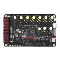
3.2 UART MODE
When using a driver in UART mode, connect the jumpers beneath that driver as show in the
image below.
 Loading...