4. CONNECTIONS AND CONTROLS
4.1. Transmitter Connections and Controls
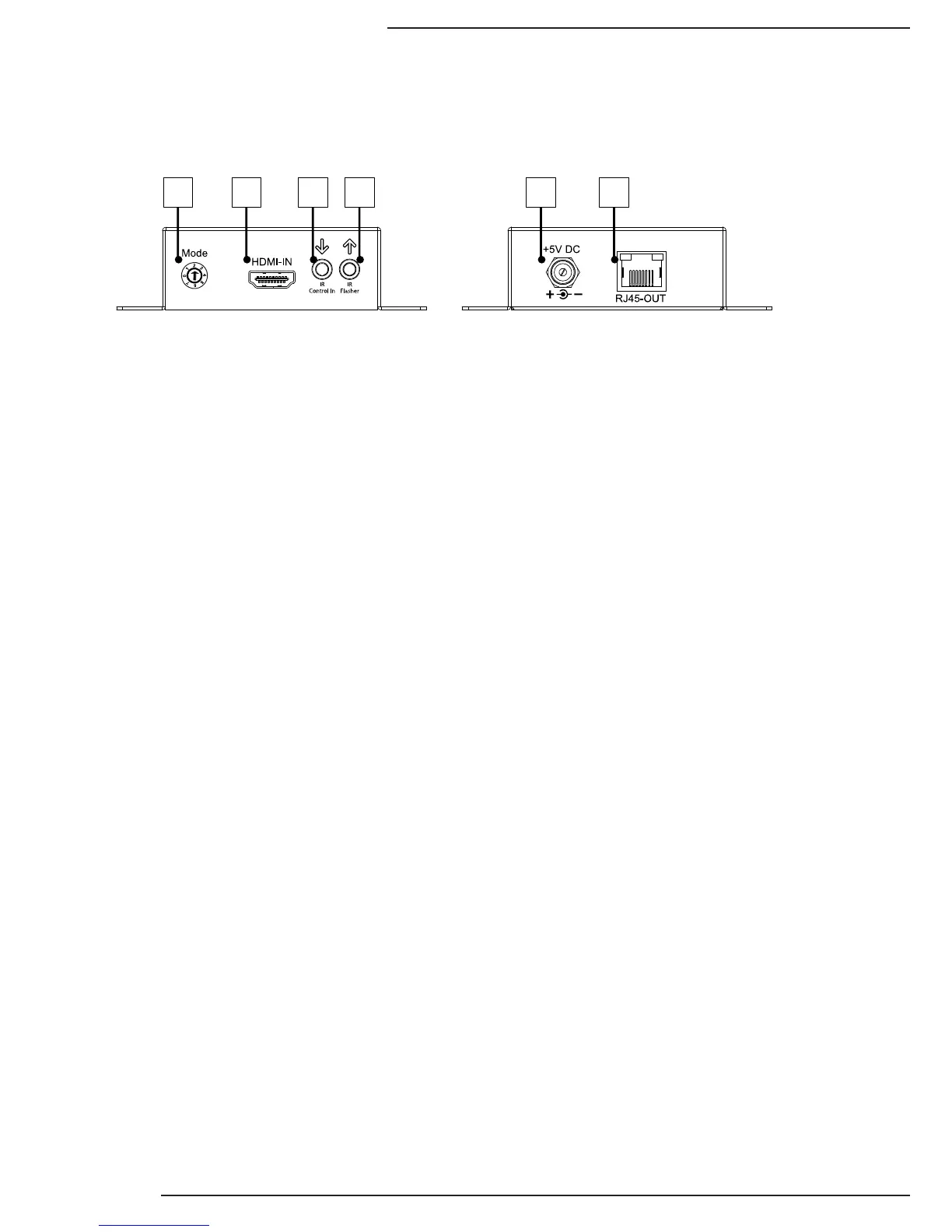
1. EDID Mode Setting
7 position rotary switch that provides selection of 6 pre-congured EDIDs and
learning. See section: 6.3 EDID Conguration.
2. HDMI In from Source (HDMI)
Connect an HDMI cable to the HDMI output of the source component.
3. IR Control In (3.5mm {1/8”} Mono)
Connect an IR Control System to send IR signals to the Receiver in the remote
location. See Section 5.2.1 for details.
4. IR Flasher Out (3.5mm {1/8”} Mono)
Connect an IR asher to send IR control signals from the Receiver to an
Automation System or Source Component. See Section 5.2.3 for details.
5. Latch-Locking Power Jack
Connect to the included 5V DC 4A Power Supply.
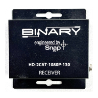
6. HD Link (RJ45)
Connect to RJ45 1cat input of the Receiver; this connection follows standard TIA/
EIA-568B. While 568A can be used, its use will degrade performance due to the
nature of the signals being transmitted.
1 2 3 4 5 6