pg.9
Connection Precautions!
• Before connecting an IR Receiver or an IR Automation System, verify that the
B-320-1CAT-HDIR is OFF to avoid damaging the unit.
• The IR Receiver In (3.5mm {1/8”} Stereo) on the Receiver provides 9V power
to power IR Receivers. This voltage can damage ashers and Automation
Systems. Take caution before plugging an IR Flasher or IR Receiver into the
respective IR sockets. The Manufacturer’s Warranty will not cover any damage
that may occur. See IR Control Connections section for proper cabling.
• Pin out congurations for IR Receivers and Automation Systems vary. Before
connecting to this input, review this section carefully in order to match the pin
outs for the B-320-1CAT-HDIR.
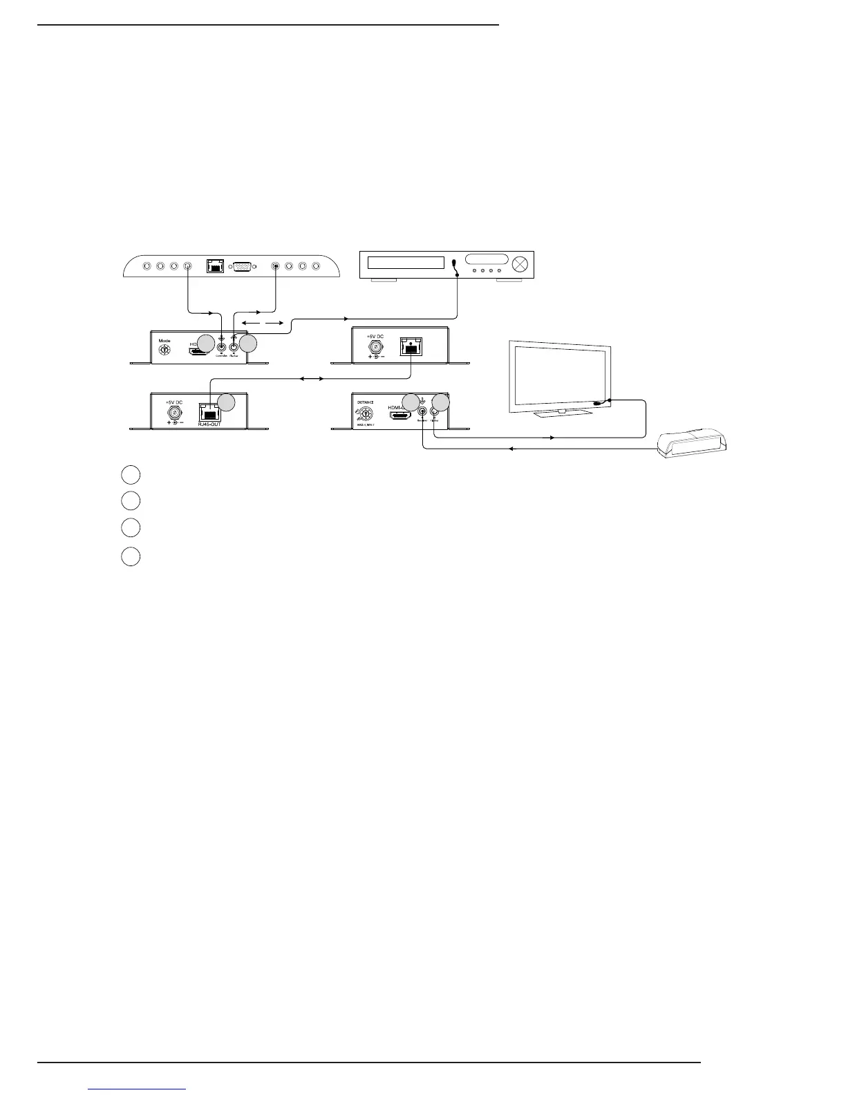
5.2. IR Control Connections
Bi-directional IR signals are transmitted between the B-320-1CAT-HDIR
Transmitter and Receiver over the Cat5e/6 cable. How the IR connections
function varies on the Transmitter and Receiver based on the common use
cases for sending and receiving IR. This section outlines the operation of IR
on the Transmitter and Receiver.
A
BD
A IR Control In Transmitter-See Section 5.2.1
C IR Flasher Out -See Section 5.2.3
D HD Link (RJ45)-See Section 5.1
C
C
B
IR Receiver In Receiver-See Section 5.2.2