pg.7
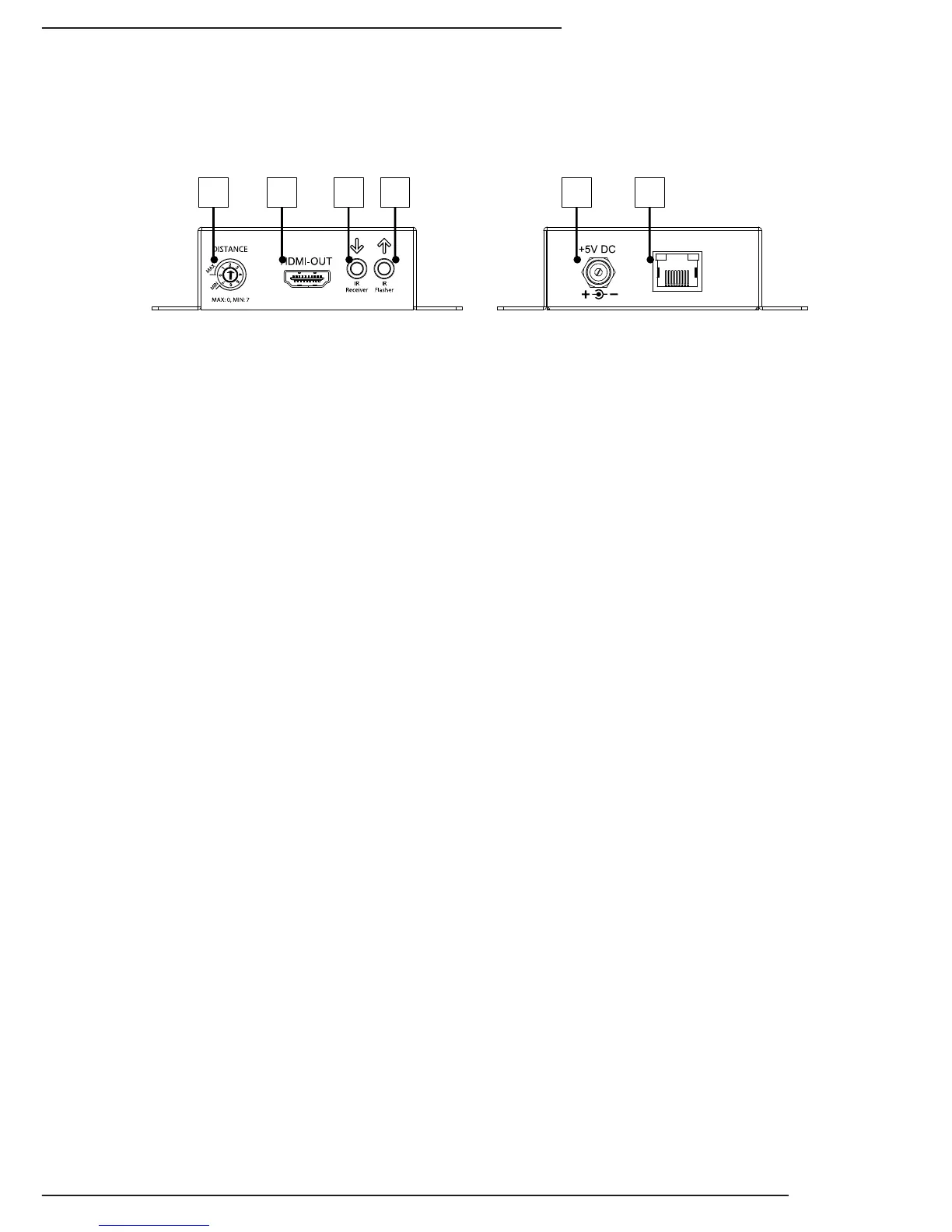
4.2. Receiver Connections and Controls
1. Distance Control
8 position rotary switch that provides equalization control to prevent over or
under loading the HD signal. See Distance Calibration for more details.
2. HDMI Out to Display (HDMI)
Connect an HDMI cable to the HDMI output of the source component.
3. IR Receiver (3.5mm {1/8”} Stereo)
Connect an IR Control System to send IR signals to the Receiver in the remote
location. See Section 5.2.1 for details.
4. IR Flasher Out (3.5mm {1/8”} Mono)
Connect an IR asher to send IR control signals from the Receiver to an
Automation System or Source Component. See Section 5.2.3 for details.
5. Latch-Locking Power Jack
Connect to the included 5V DC 4A Power Supply.
6. HD Link (RJ45)
Connect to RJ45 1cat input of the Receiver; this connection follows standard TIA/
EIA-568B. While 568A can be used, its use will degrade performance due to the
nature of the signals being transmitted.