SPRAY TECHNIQUE
The first requirement for a good resul-
tant finish is the proper handling of the
gun. The gun should be held perpendic-
ular to the surface being covered and
moved parallel with it. The stroke
should be started before the trigger is
pulled and the trigger should be released
before the stroke is ended. This gives
accurate control of the gun and fluid.
The distance between gun and surface
should be 6 to 12 inches depending on
fluid and atomizing pressure. The fluid
deposited should always be even and
wet. Lap each stroke over the preceding
stroke to obtain a uniform finish.
GENERAL SPRAY
INSTRUCTIONS
To reduce overspray and obtain maxi-
mum efficiency, always spray with the
lowest possible fluid/air pressure that
produces an acceptable spray pattern.
Excessive atomizing air pressures can
increase overspray, reduce transfer effi-
ciency, and with some materials, result
in poor finish quality from dry spray.
Atomizing air pressures should not
exceed 10 psi. See table on page 6, dia-
gram on page 2 and Regulatory Note on
page 8.
For best results, use 3 to 6 psi fluid
pressure. Higher than 6 psi fluid pres-
sure may be required for heavy-bodied
materials. Low fluid pressures will
produce a narrower than normal spray
pattern. Generally use 30-35 psi air at
gun inlet (see page 6). Unusually heavy,
difficult to atomize fluids may require
up to 50 psi air at gun inlet.
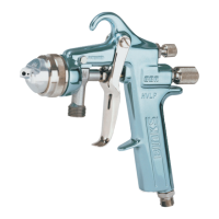
CONTROLLING THE FAN SPRAY
The fan spray is controlled by means of
the side port control assembly (7).
Turning this control clockwise until it is
closed will give a round spray; turning it
counterclockwise will widen the spray
into a fan shape. The fan spray can be
turned anywhere through 360 ° by posi-
tioning the air nozzle (2) relative to the
gun. To accomplish this, loosen retain-
ing ring (1), position nozzle (2), then
tighten retaining ring (1).
CONTROLLING THE FLUID
FLOW
When used with a pressure assisted cup,
an increase in air pressure will increase
the rate of flow. When fed from a pres-
sure supply, an increase in the fluid
pressure will increase the rate of flow.
Correct fluid nozzle size should be
selected for correct fluid flow rate. The
fluid control knob (23) may be used to
restrict the fluid nozzle (3) opening and
reduce the fluid flow as necessary.
AIR NOZZLE, FLUID NOZZLE,
NEEDLE ASSEMBLY
1. All nozzles and needles are preci-
sion made. They should be handled
with care.
2. Except as described in
“ADJUSTING THE NEEDLE
ASSEMBLY”, do not make any
alterations in the gun. To do so
could cause finishing difficulties.
3. To clean nozzles, soak them in sol-
vent to dissolve any dried material,
then blow them clean with air.
4. Do not probe any of the holes in the
nozzles with metal instruments.
If probing is necessary, use only a
tool that is softer than brass.
ADJUSTING THE NEEDLE
ASSEMBLY (20).
1. Remove the fluid control knob (23)
and the blue spring (18).
2. Pull the needle assembly out approx-
imatley 1-1/4 inches.
3. Loosen the needle cap (22).
4. Screw the needle assembly locknut
(21) out for more trigger movement,
in for less trigger movement.
5. Adjust the needle assembly so that
when the trigger (35) moves, the
spindle assembly (17) moves 1/16 to
3/32 of an inch before the needle
assembly moves.
6. Tighten the needle cap.
7. Re-assemble.
TROUBLESHOOTING
Faulty Spray
A faulty spray pattern is often caused by
improper cleaning resulting in dried
materials around the fluid nozzle tip or
in the air nozzle. Soak these parts in
thinners to soften the dried material and
remove with a brush or cloth.
If either the air nozzle (2) or fluid noz-
zle (3) are damaged, these parts must be
replaced before perfect spray can be
obtained.
Intermittent Spray
If the spray flutters, it is caused by one
of the following faults:
1. Insufficient fluids available. Check
supply and replenish if necessary.
2. Pressure vent tube from gun body
to pressure assist cup is loose or
leaking.
3. Check valve in pressure vent tube is
stuck or blocked.
4. Pressure assist cup cover not
sufficiently tight or cover gasket
defective.
5. Insufficient fluid pressure from
standard pressure pots.
7
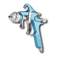
OPERATING THE MACH 1
HVLP SPRAY GUN
NOTE
To reduce overspray and obtain
maximum efficiency always spray
with the lowest possible atomizing
air pressure.
CAUTION
Overtightening may damage the
threads and make future adjust-
ments difficult.
!
CAUTION
Never use metal instruments to clean
the air or fluid nozzles. These parts
are carefully machined and any dam-
age to them will cause faulty spray.
!
 Loading...