VIII. MAINTENANCE AND SERVICE- CONT.
58
G- DISASSEMBLY & REASSEMBLY INSTRUCTIONS
If the Crossvent is mounted within another piece of equipment, refer to the service manual for that equipment as provided
by the manufacturer for removal of the Crossvent.
WARNING: High voltage is present at the backlight connector (JBL) when power is
on.
CAUTION: All safety measures must be observed when servicing this device. In particular,
the ventilator must be turned off and the power supply disconnected.
CAUTION: With the PC Board removed, great care should be taken to protect the board
from stray voltages, static electricity, and any other environmental concerns that may damage
the board. Always handle the board with care and be sure you and your work surface are
properly grounded.
Note: Prior to disposal of any component, with particular attention to the battery and PCB, check with
your local controlling authority for disposal regulations.
Note: Whenever the battery is disconnected, the battery gauge must be reset. Refer to Battery Removal
& Replacement instructions in this section.
1. REAR PANEL
NOTE: The battery is loose once the rear panel is removed.
1. Remove the four (4) long screws located around the perimeter of the rear panel. These extend to the front bezel.
2. Remove the two small screws between the circuit connection fittings.
3. Remove the patient outlet fitting.
4. Remove the rear panel and unplug the power and O
2
jack cables.
5. Reverse order to re-install. Be sure the battery cable grommet is set properly into the notch in the battery
compartment and no other wires or tubes are in a position to be pinched when the panel is installed.
2. BATTERY REMOVAL & REPLACEMENT
CAUTION: Only replace the battery pack with Bio-Med Devices part #PRT2268. Do not
substitute.
NOTE: After installing a new battery, it must be discharged, the battery gauge must be reset in the
calibration menu and the battery then fully charged and discharged as outlined in this procedure.
1. Remove the rear panel.
2. Remove the grommet on the battery wires from the notch in the
battery compartment and lift the battery out of the battery enclosure.
Unplug the battery connector.
3. Verify four 1/16” rubber pads similar to those supplied with the new
battery are adhered to the bottom (side closest to the PC Board) of the
battery enclosure. If there are none, then adhere the four new 1/16” pads
to the inside of the enclosure so that they will be under the center of each
corner cell of the battery pack when it is installed. There should also be a
1/16” thick pad on the inside of the rear panel within the cutout in the
battery enclosure gasket. If there is none, use the pad included with the
battery and adhere as shown.
4. Place the battery in the enclosure so that the label on the battery is facing
the rear panel.
5. Plug the connectors together outside the enclosure and work the grommet on the wire into the notch in the side of
the enclosure.
6. Plug the external power cables together and plug the O2 jack into the Connector board on the side of the battery
enclosure. Replace the rear panel and six screws. Take care that the grommet remains in the notch when the panel
is replaced and no wires or tubing are pinched.
If this is a new battery, a battery other than the original battery or if the current battery has been disconnected, then
proceed with the following steps to re-program the battery gauge to the battery.
7. Turn on the Crossvent. Be sure the external power supply is not connected to the unit. If the battery is already
depleted and the unit will not power on without the external power supply, then go to Step 11.
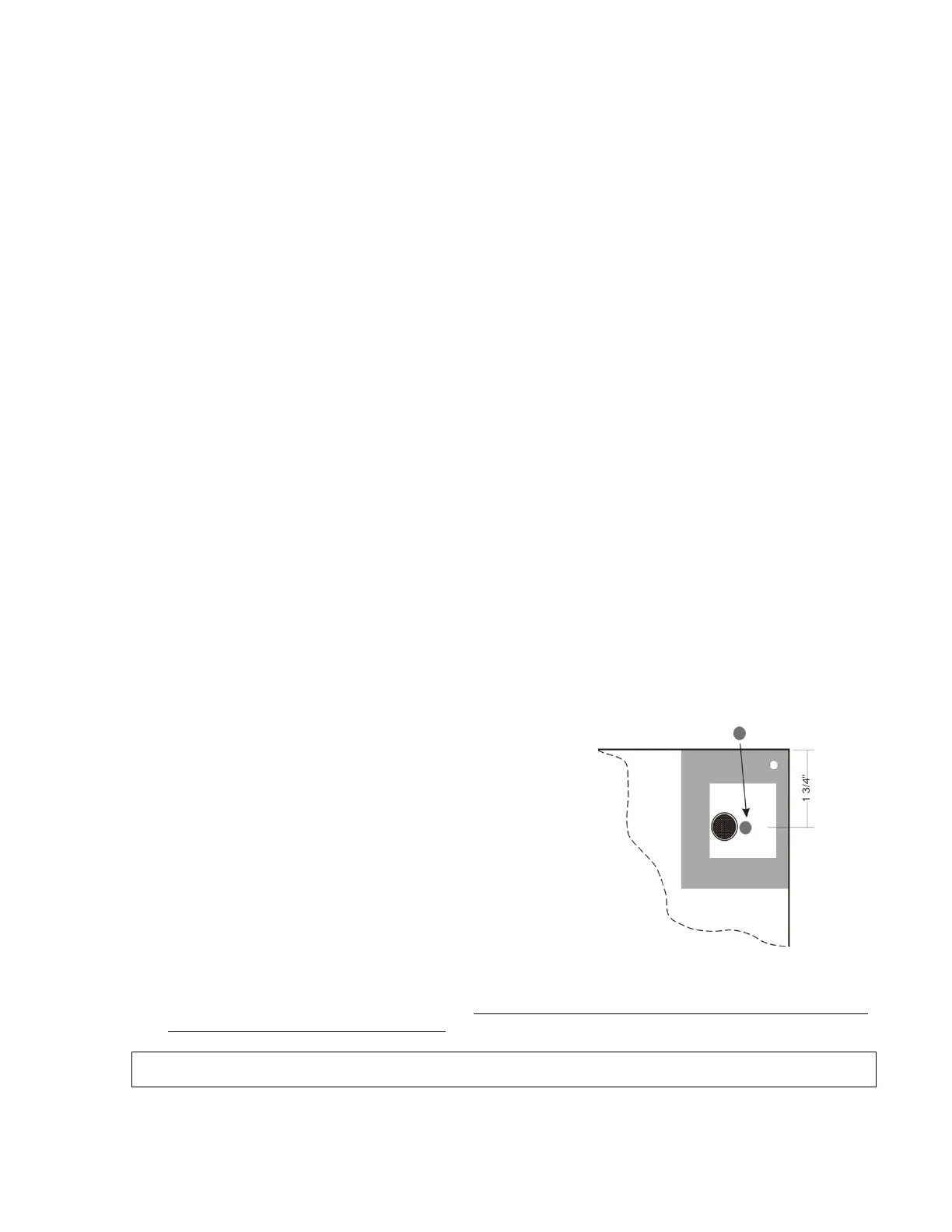
“C” cell
Adhere pad as shown
1/16” thick