Motherboard Manual
12
2.7 Headers & Connectors
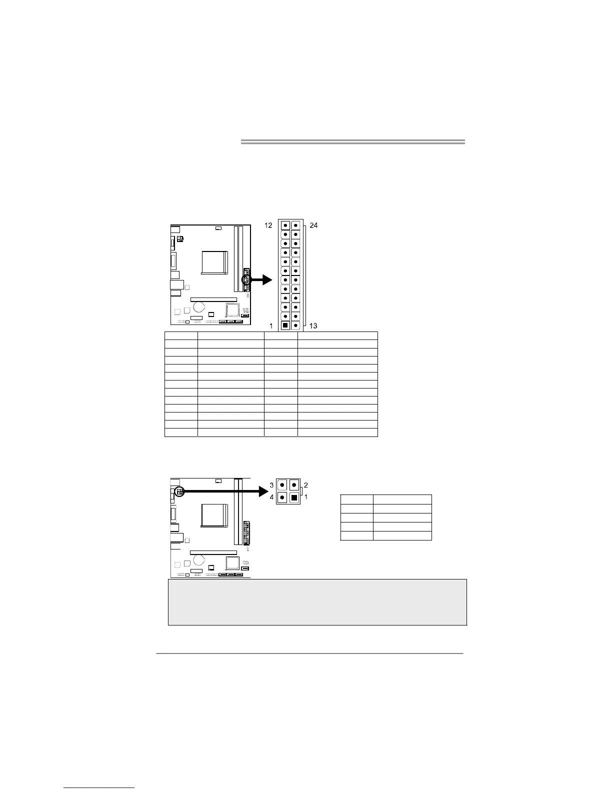
ATXPWR1: ATX Power Source Connector
For better compatibility, we recommend to use a standard ATX 24-pin power
supply for this connector. Make sure to find the correct orientation before
plugging the connector.
Pin Assignment Pin Assignment
13 +3.3V 1 +3.3V
14 -12V 2 +3.3V
15 Ground 3 Ground
16 PS_ON 4 +5V
17 Ground 5 Ground
18 Ground 6 +5V
19 Ground 7 Ground
20 NC 8 PW_OK
21 +5V 9 Standby Voltage+5V
22 +5V 10 +12V
23 +5V 11 +12V
24 Ground 12 +3.3V
ATXPWR2: ATX Power Source Connector
This connector will provide +12V to CPU power circuit.
Pin Assignment
1 +12V
2 +12V
3 Ground
4 Ground
Note1: Before you power on the system, please make sure that both ATXPWR1 and
ATXPWR2 connectors have been plugged-in.
Note2: Insufficient power supplied to the system may result in instability or the
peripherals not functioning properly. Use of a PSU with a higher power output is
recommended when configuring a system with more power-consuming devices.