Motherboard Manual
8
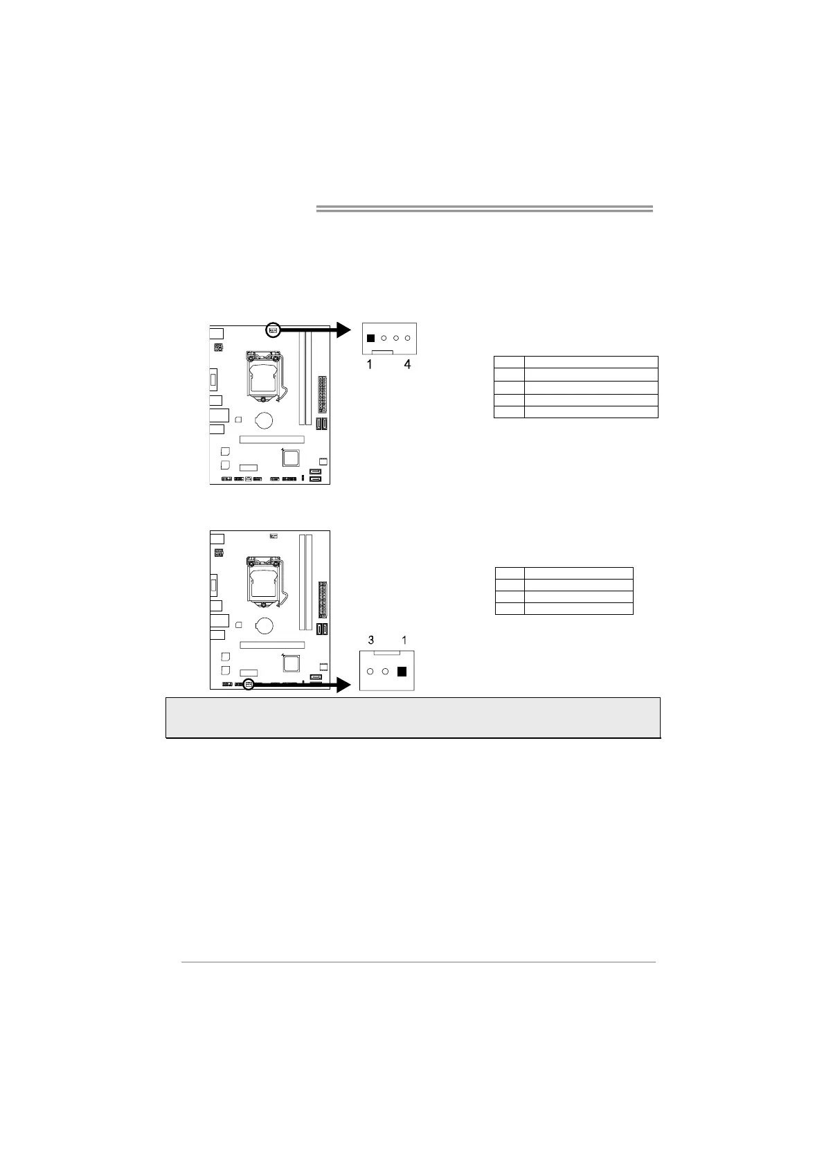
2.3 Connect Cooling Fans
These fan headers support cooling-fans built in the computer. The fan cable and
connector may be different according to the fan manufacturer.
CPU_FAN1: CPU Fan Header
Pin Assignment
1 Ground
2 +12V
3 FAN RPM rate sense
4 Smart Fan Control (By Fan)
SYS_FAN1: System Fan Header
Pin Assignment
1 Ground
2 +12V
3 FAN RPM rate sense
Note: CPU_FAN1, SYS_FAN1 support 4-pin and 3-pin head connectors. When connecting with
wires onto connectors, please note that the red wire is the positive and should be connected to
pin#2, and the black wire is Ground and should be connected to pin#1(GND).