EasyManua.ls Logo

Biostar P4M900 Micro 775 User Manual

Biostar P4M900 Micro 775
93 pages
To Next Page IconTo Next Page
Page #1 background imageLoading...
Page #1 background image
P4M900 Micro 775 Setup Manual
FCC Information and Copyright
This equipment has been tested and found to comply with the limits of a Class
B digital device, pursuant to Part 15 of the FCC Rules. These limits are designed
to provide reasonable protec tion against harmful interference in a residential
installation. This equipment generates, uses and can radiate radio frequency
energy and, if not installed and used in accordance with the instructions, may
cause harmful interference to radio communications. There is no guarantee
that interference will not occur in a particular ins tallation.
The ve ndo r makes no represe nta tions o r wa rranties with respec t to the
contents here and specially disclaims any implied warranties of merchantability
o r fi tnes s fo r a ny p u rp ose . F urt he r t he ve nd o r res e rves t he ri ght to rev is e t h is
publication and to make changes to the contents here without obligation to
notify any party beforehand.
D uplica tion of this publication, in part or in whole, is not allowed without first
obtaining the vendor’s approval in writing.
The content of this user’s manual is subject to be changed without notice and
we will not be res ponsible for any mis takes found in this users manual. All the
brand and product names are trademarks of their respective companies.
Table of Contents

Questions and Answers:

Biostar P4M900 Micro 775 Specifications

General IconGeneral
BrandBiostar
ModelP4M900 Micro 775
CategoryMotherboard
LanguageEnglish

Summary

CHAPTER 1: INTRODUCTION

1.1 BEFORE YOU START

Instructions to follow before installing the motherboard, focusing on environment and safety.

1.3 MOTHERBOARD FEATURES

Detailed specifications and features of the motherboard, comparing versions.

1.4 REAR PANEL CONNECTORS (FOR VER 5.X)

Diagram and explanation of rear panel connectors for version 5.x.

1.5 REAR PANEL CONNECTORS (FOR VER 6.X)

Diagram and explanation of rear panel connectors for version 6.x.

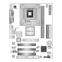
1.6 MOTHERBOARD LAYOUT (FOR VER 5.X)

Visual diagram showing the layout of components on the motherboard for version 5.x.

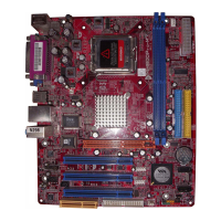
1.7 MOTHERBOARD LAYOUT (FOR VER 6.X)

Visual diagram showing the layout of components on the motherboard for version 6.x.

CHAPTER 2: HARDWARE INSTALLATION

2.1 INSTALLING CENTRAL PROCESSING UNIT (CPU)

Step-by-step guide on how to install the CPU onto the motherboard socket.

2.2 FAN HEADERS

Explains the purpose and pin assignments of CPU and system fan headers.

2.3 INSTALLING SYSTEM MEMORY

Instructions for installing memory modules into the DIMM slots and memory capacity details.

2.4 CONNECTORS AND SLOTS

Details on the Floppy Disk Connector (FDD1) and Hard Disk Connectors (IDE1/IDE2).

PCI-EX16: PCI-Express x16 Slot

Information about the PCI-Express x16 slot specifications and bandwidth.

PCI-EX1_1: PCI-Express x1 slots

Information about the PCI-Express x1 slots specifications and bandwidth.

PCI1~PCI2: Peripheral Component Interconnect Slots

Details on the standard PCI slots and their function as expansion card slots.

CHAPTER 3: HEADERS & JUMPERS SETUP

3.2 DETAIL SETTINGS

Configuration details for specific motherboard headers, starting with the Front Panel Header.

ATX Power Source Connector: JATXPWR1

Details on connecting the 24-pin ATX power supply connector to JATXPWR1.

JATXPWR2: ATX Power Source Connector

Information about the ATX power source connector for CPU power.

JUSB2/JUSB3: Headers for USB 2.0 Ports at Front Panel

Configuration for connecting USB 2.0 ports at the front panel.

JUSBV1/JUSBV2: Power Source Headers for USB Ports

Details on power source headers for USB ports and jumper settings.

JAUDIO 2: Front Panel Audio Header

Configuration for the front panel audio header, connecting front audio output.

JCMOS1: Clear CMOS Header

Procedures for clearing CMOS data and resetting BIOS settings.

JSATA1~JSATA2: Serial ATA Connectors

Information about the Serial ATA connectors and their interface specifications.

CHAPTER 4: USEFUL HELP

4.1 DRIVER INSTALLATION NOTE

Guide on installing drivers from the provided CD for optimal system performance.

A. Driver Installation

Steps to install motherboard drivers via the setup guide on the driver CD.

4.2 AWARD BIOS BEEP CODE

Table of AWARD BIOS beep codes and their corresponding error meanings.

A. BIOS Update

Procedures for recovering the BIOS using the Boot-Block function.

B. CPU Overheated

Troubleshooting steps for system shutdown due to CPU overheating.

4.4 TROUBLESHOOTING

Common troubleshooting scenarios and their solutions for system issues.

CHAPTER 5: WARPSPEEDER™

5.3 INSTALLATION

Step-by-step guide for installing the WarpSpeeder utility software.

5.4 WARPSPEEDER™

Details on using WarpSpeeder features, including the tray icon and main panel.

2. Main Panel

Describes the main interface panel of the WarpSpeeder utility and its features.

3. Voltage Panel

Details on adjusting CPU core and memory voltages using the WarpSpeeder Voltage Panel.

4. Overclock Panel

Information on using the Overclock Panel for real-time overclock adjustments and recovery options.

5. Hardware Monitor Panel

Explains how to monitor system hardware status in real-time using the WarpSpeeder Hardware Monitor.

P4M900 Micro 775 BIOS Setup

BIOS Setup

Overview of the BIOS setup utility and its purpose.

Using Setup

Guide on navigating the BIOS setup utility using keyboard controls.

1 Main Menu

Describes the main menu of the Award BIOS CMOS Setup Utility.

Standard CMOS Features

Submenu for configuring industry-standard system options.

Advanced BIOS Features

Submenu for configuring advanced BIOS features.

Advanced Chipset Features

Submenu for configuring specific chipset features.

Integrated Peripherals

Submenu for configuring IDE, hard drive, and I/O features.

Power Management Setup

Submenu for configuring system power management settings.

PnP/PCI Configurations

Submenu for configuring Plug and Play and PCI options.

PC Health Status

Submenu for monitoring the system's hardware status.

Performance Booster Zone

Submenu for adjusting CPU voltage, clock, and performance settings.

Load Optimized Defaults

Option to reload factory default BIOS settings.

Upgrade BIOS

Functionality to upgrade the system's BIOS firmware.

2 Standard CMOS Features

Section detailing various system configuration items like date, time, and drives.

3Advanced BIOS Features

Covers advanced BIOS settings including boot sequence and system features.

CPU Feature

Settings related to CPU thermal management, bus ratio, and voltage.

4 Advanced Chipset Features

Configures specific chipset features managing bus speeds and memory access.

5 Integrated Peripherals

Configures integrated peripherals on the motherboard.

Super IO Device

Configuration for Super I/O devices, including FDC, serial, and parallel ports.

6 Power Management Setup

Configures system power saving and power up/down features.

7 PnP/PCI Configurations

Configuration of the PCI bus system and I/O devices.

8 PC Health Status

Monitors system hardware status, including temperatures, fan speeds, and voltages.

9 Performance Booster Zone

Zone for optimizing system performance through clock and voltage adjustments.

DRAM Clock/Drive Control

Controls DRAM clock and drive settings.

CPU CLOCK

Selects CPU clock and allows CPU overclocking.

Related product manuals