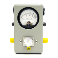
Directional RF Thruline® Wattmeter, Series 4410
3
Theory Of Operation
On any uniform RF line section there are voltages, currents and standing waves
present when RF power is applied. These are the results of two traveling waves,
forward and reflected. The characteristic impedance of these lines is a pure
resistance, usually 50 ohms for useful lines. The main RF circuit of the
wattmeter is a short, precision type line section whose characteristic impedance
is 50 ohms.
Coupling Circuit
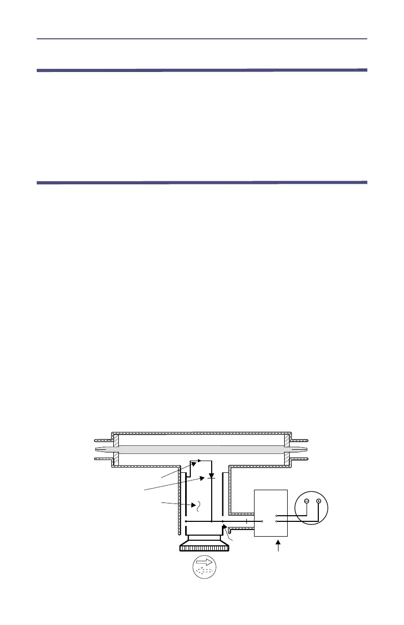
The coupling circuit which samples the traveling waves is in the plug-in element.
The circuitry of the element and its relationship to the other components of the
wattmeter are illustrated in figure 1. Energy is absorbed in the coupling circuit
of the element both by mutual inductance and by capacitance from the
traveling RF waves of the line section. These inductive currents flow according
to the direction of the traveling waves producing them, whereas the capacitive
portion of these currents is independent of the direction. It is, therefore,
apparent that the two currents produced from the waves traveling in one
direction add in phase, while the currents produced from the waves traveling in
the opposite direction subtract in phase. The arrow on the Plug-In Element
indicates the additive direction of wave travel. The element is so designed that
the currents from the wave components traveling in the opposite direction of
the arrow cancel each other out almost completely, making the element highly
insensitive to the reverse wave direction. The additive direction signal, which is
to be measured, is detected from which an accurate power reading is obtained.
Because of the highly directional characteristics of the element, the resultant
direct current which is sensed by the microammeter indicates the power level
of only the RF waves traveling in the arrow direction.
Figure 1 Element Schematic Diagram
RF Coaxial Line
XMTR
or
LOAD
LOAD
or
XMT
Directional Coupling
Diode
Detector Element
Meter
DC Contact
Circuit Board
 Loading...