Directional RF Thruline® Wattmeter, Series 4410
11
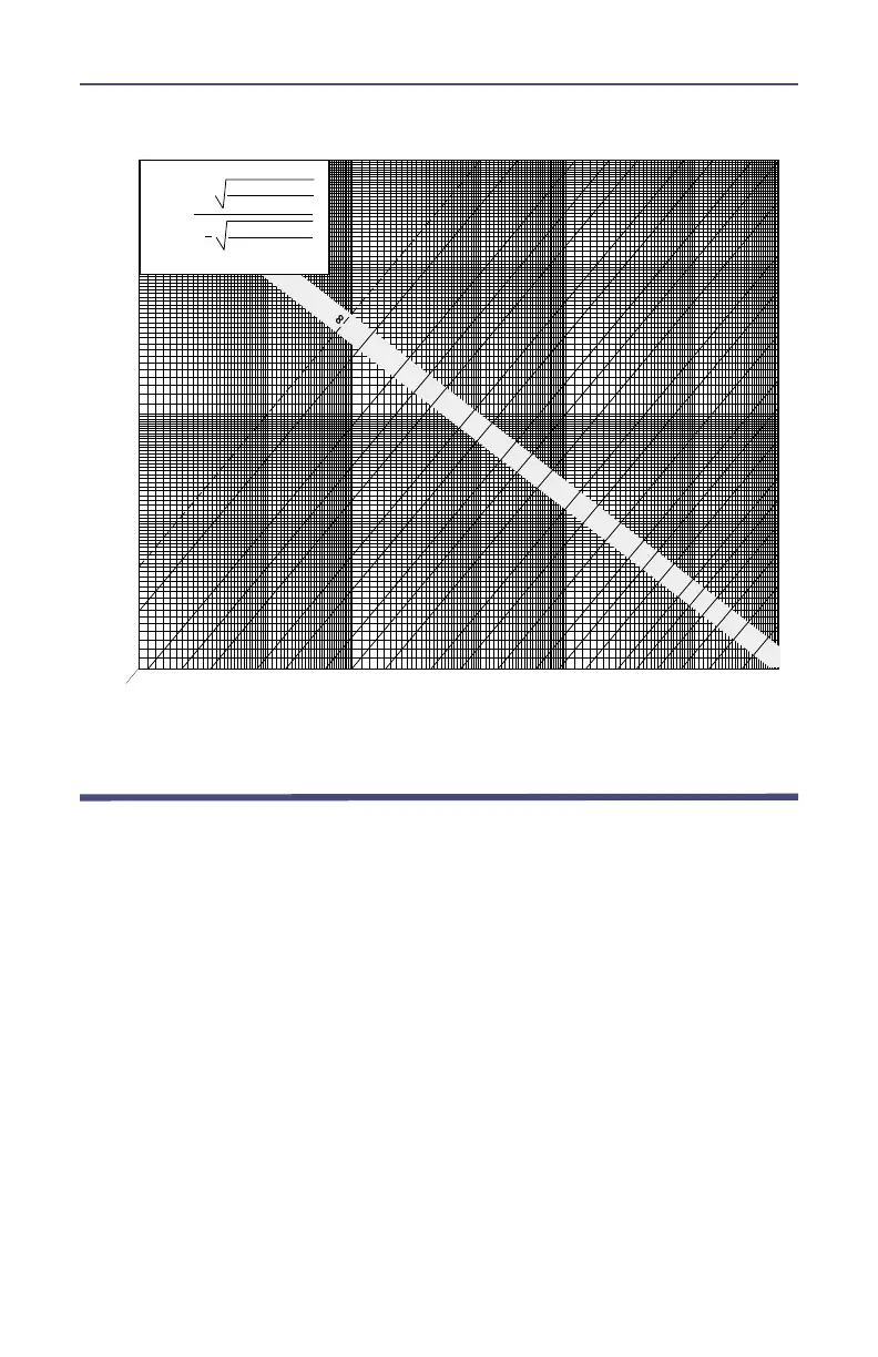
Figure 8 VSWR Conversion Nomograph
10
15
20
0.5
1.0 1.5
2.0
2.5
3.0
4.0
5.0
25
30 40
50
100 150 200
300 400
50
.2
.4
.6
.8
1.0
1.2
1.4
1.6
1.8
2.0
4
6
8
10
12
14
16
18
20
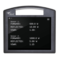
VSWR=
1+
Reflected Power
Forward Power
Reflected Power
Forward Power
1
FORW ARD POWER - W A TTS
REFLECTED POWER - WATTS
3.0
2.5
2.0
1.6
1.5
1.4
1.3
1.25
1.20
1.16
1.14
1.12
1.10
1.09
1.08
1.07
1.06
1.05
1.8
10
4.0
VSWR
Shutdown
When all measurements are completed, be sure to turn the range switch to the
OFF position. Leaving the switch on one of the power ranges will not harm the
circuit in any way but it will shorten the battery life. Note that there is a battery
test position on the range selector switch. This battery test position is provided
to conveniently check the condition of the battery each time the Series 4410 is
switched on.
Always be sure the transmitter power is off before disconnecting the unit from
the transmission line.
 Loading...