32
LOWER REMOVABLE WHEEL
INSTALLATION AND REMOVAL INSTRUCTIONS
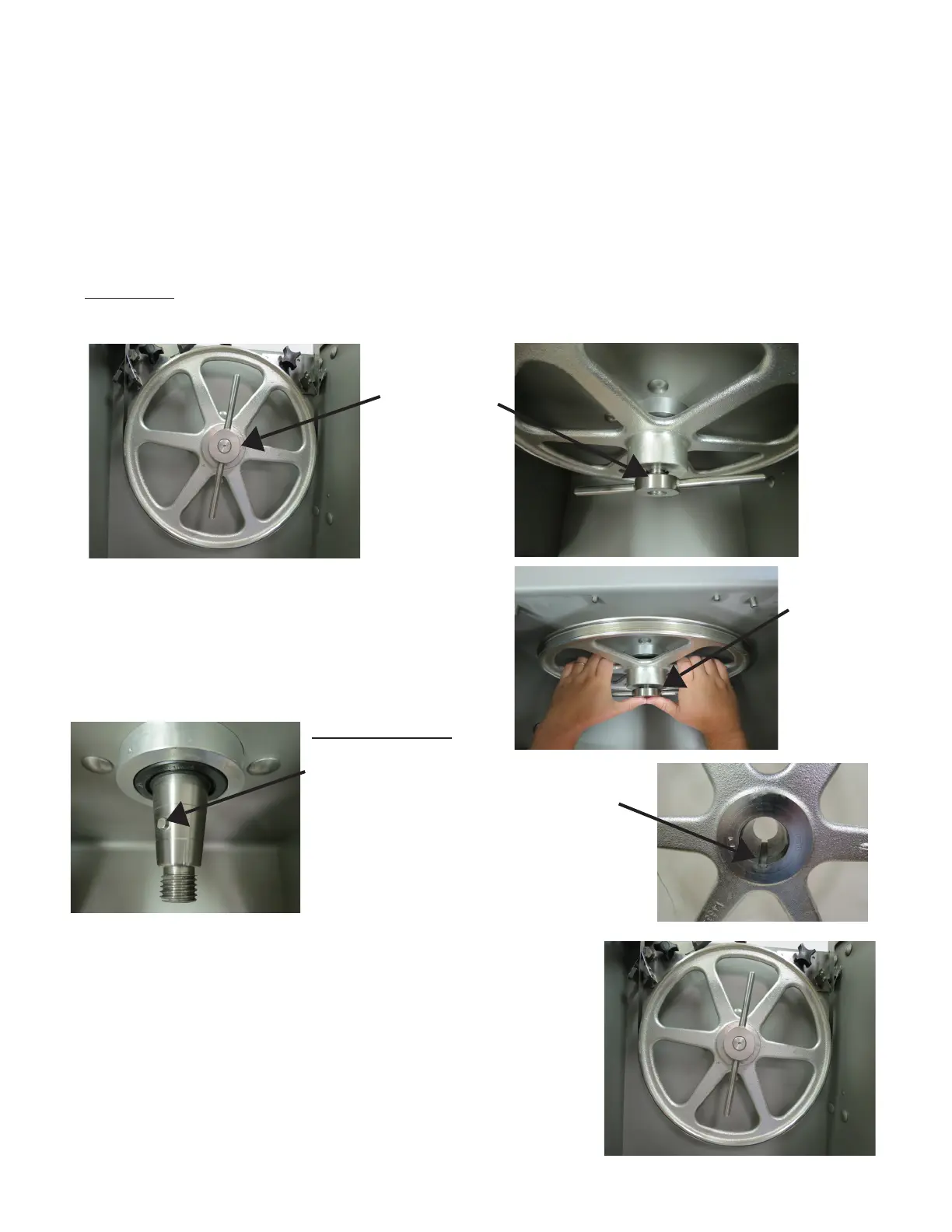
INSTALLATION
There is an alignment pin on the lower
shaft. And a mating alignment groove in
the hub of the lower wheel. Align the two
as the wheel is being installed on the
tapered shaft.
NOTE:
TO ENSURE PROPER SAW
WHEEL ALIGNMENT,
WHEEL MUST BE
REINSTALLED ON SAME
MACHINE IT WAS
REMOVED.
Replace the
T-Handle Lock
HAND TIGHTEN
ONLY
Reassemble the machine.
14746
T-Handle
Lock
T-Handle
Loosened
Using thumbs for leverage, pull wheel toward you
with an even-smooth motion. Wheel is mounted in
slip t fashion on a tapered shaft. When the wheel is
loose, complete removing T-Handle lock and wheel.
ALWAYS Turn Off, Unplug Machine From Power Source and Perform Lockout/Tagout Procedure to the
Machine BEFORE Cleaning or Servicing.
Follow disassembly procedures in the Cleaning Section of the Operating and Service Manual.
Removal of the Lower Wheel will be the last procedure.
14746
T-Handle
Lock
REMOVAL
Loosen Item No. 14746, T-Handle Lock. DO NOT REMOVE COMPLETELY FROM SHAFT.