ML0038 September 27, 2017 - 24 - Copyright 2017 Bitronics, LLC
3.0 BACK PANEL & WIRING
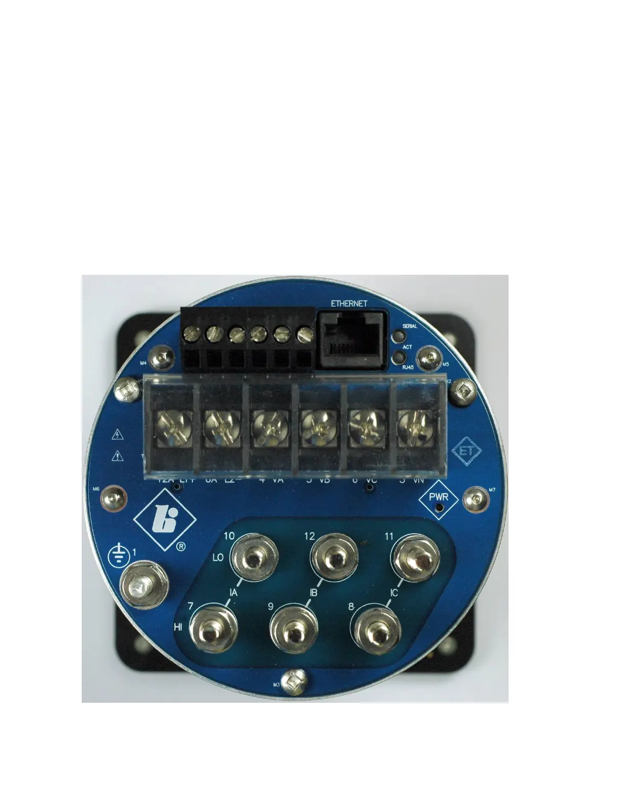
The rear view of the M350 is shown in figure 3 with the option port shown (removable
terminal block at the top), which may be selected at order time, as either, the serial
communication option, the 0-1mA analog transducer output option, or the 4-20mA
analog transducer output option. However, it is also possible to have a meter without
this option port. Please note that voltage terminals 3 – 6 are not active on model A3
ammeter, only the V3 voltmeter. Current terminals are not present on model V3
voltmeter.
See Appendix A1 for detailed wiring diagrams covering the CT or VT measurement
inputs. Refer to the appropriate section in this user manual when wiring either the
serial communication option, or either analog transducer output option, whichever
applies to the option port for your meter.
Figure 3 – Rear View M350 A3